A stepper motor’s purpose is to rotate through a precise angle and halt. The speed and torque of the rotation are secondary concerns. As long as the stepper rotates through the exact angle and stops, its mission is accomplished. Each turn is called a step, and common step angles include 30°, 15°, 7.5°, 5°, 2.5°, and 1.8°.
Due to their simplicity and precision, stepper motors are popular in electrical devices. Analog clocks, manufacturing robots, and printers (2D and 3D) rely on steppers for motion control. An important advantage is that the controller doesn’t have to read the stepper’s position to determine its orientation.
If the stepper is rated for 2.5°, each control signal will turn the rotor through an angle of 2.5°. For many applications, we want the step angle to be as small as possible. The smaller the motor’s step angle, the greater its angular resolution .
Another important figure of merit is torque, particularly holding torque . A stepper motor is expected to hold its position when it comes to a halt, and holding torque identifies the maximum torque it can exert to maintain its position.
Types of Stepper Motor
Modern stepper motors can be divided into three categories:
- Permanent motor (PM) — High torque, poor angular resolution
- Variable reluctance (VR) — Excellent angular resolution, low torque
- Hybrid (HY) — Combines structure of PM and VR steppers, provides good torque and angular resolution
This article examines these categories in detail. In each case, I’ll discuss the motor’s fundamental operation and present its advantages and disadvantages. The next article explains how steppers can be controlled with electrical circuits.
Permanent Magnet (PM) Stepper Motors
Small and reliable, permanent magnet (PM) steppers are popular in embedded devices such as disk drives and computer printers.
PM steppers have a lot in common with the brushless DC (BLDC) motors discussed in the preceding article. In fact, you can think of a PM stepper as a BLDC whose windings are energized to provide discrete rotation instead of continuous rotation.
Structure: The preceding article introduced the brushless DC motor and its two subcategories: inrunners and outrunners. PM steppers are similar to inrunners in many respects, and a good way to introduce them is to compare and contrast them with inrunner BLDCs. Figure 1 illustrates the internal structure of a simple PM stepper. There are five important similarities between PM steppers and inrunner BLDCs:
- Neither motor has a brush or a mechanical commutator (all steppers discussed in this book are brushless).
- The rotor is on the inside, with permanent magnets mounted on its perimeter.
- The stator is on the outside, with electromagnets (called windings) inside slots.
- The controller energizes the windings with pulses of DC current.
- Many of the windings are connected together. Each group of connected windings forms a phase.
PM steppers are brushless and receive DC pulses from the controller. For this reason, they could be classified as BLDCs. But in this article, as in other literature, we’ll only employ the term BLDC for motors that aren’t specifically intended for motion control.
Let’s look at the differences between the two types of motors. Following Table contrasts the characteristics of PM steppers with those of inrunner BLDCs.
From a structural perspective, the primary difference between PM steppers and inrunners is that PM steppers have more windings and rotor magnets. As it turns out, this is necessary to make the angular resolution as small as possible. The following discussion explains why this is the case.
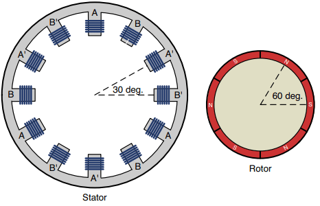
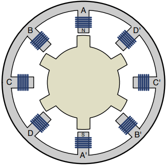
Operation: To understand how a PM stepper operates, it’s crucial to see how its step angle is determined by the number of windings and rotor magnets. This discussion focuses on the motor depicted in Figure 1 . Its stator has 12 windings and its rotor has six magnets mounted on its perimeter.
PM steppers are generally two-phase motors. In the figure, the different phases are denoted A and B. The windings labeled A’ and B’ receive the same current as those labeled A and B, but in the opposite direction. That is, if A behaves as a north pole, A’ behaves as a south pole.
Each winding has one of three states: positive current, negative current, and zero current. For this discussion, positive current implies a north pole and negative current implies a south pole.
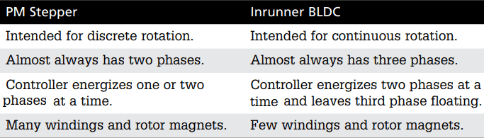
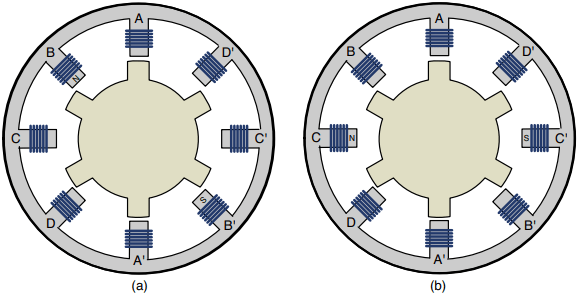
Now let’s see how these motors operate. Figure 2 illustrates a single turn of a PM stepper. In the windings, a small “N” implies that the winding behaves like a north pole due to positive current. A small “S” implies that the winding behaves like a south pole due to negative current. If a winding doesn’t have an N or S, it isn’t receiving current.
In Figure 2a , A is positive (north pole), A’ is negative (south pole), and Phase B isn’t energized. The rotor aligns itself so that its south poles are attracted to the A windings and its north poles are attracted to the A’ windings.
In Figure 2b , B is positive (north pole), B’ is negative (south pole), and Phase A isn’t energized. The rotor rotates so that its poles align with the B and B’ windings. The rotation angle equals the angle between the A and B windings, which means the rotor turns exactly 30° in the clockwise direction. This arrangement of eight windings and six poles is common for PM stepper motors, though others turn at angles of 15° and 7.5°.
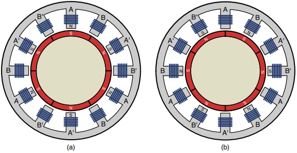
In case this isn’t clear, let’s look at a second movement. Figure 3 presents another 30° rotation of a PM stepper motor.
In Figure 3a , B is negative (south pole), B’ is positive (north pole), and A isn’t energized. The rotor is positioned so that its poles align with the B windings.
In Figure 3b , A is positive (north pole), A’ is negative (south pole), and B isn’t energized. The rotor turns exactly 30° in the clockwise direction to align itself between the A windings.
The controller’s job is to deliver current to the windings so the rotor continues turning in 30° increments. The difference in control signaling is a major difference between steppers and BLDCs.
Variable Reluctance (VR) Stepper Motors
Just as resistance determines the flow of electric current, reluctance determines the flow of magnetic flux. In a variable reluctance (VR) stepper, the rotor turns at a specific angle to minimize the reluctance between opposite windings in the stator.
The primary advantage of VR steppers is that they have excellent angular resolution. The primary disadvantage is low torque.
This section presents VR steppers in detail. I’ll explain their internal structure first and then show how they rotate as their windings are energized.
Structure: Structurally speaking, variable reluctance (VR) steppers have a lot in common with PM steppers. Both have windings on their stator and opposite windings are connected to the same current source.
However, there are two primary differences between VR steppers and PM steppers:
- Rotor — Unlike a PM stepper, the rotor in a VR stepper doesn’t have magnets. Instead, the rotor is an iron disk with small protrusions called teeth .
- Phases — In a PM stepper, the controller energizes windings in two phases. For a VR stepper, the controller energizes every pair of opposite windings independently. In other words, if the stator has N windings, it receives N/2 signals from the controller.
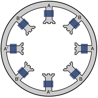
Figure 4 illustrates the rotor and stator of a VR stepper. In this motor, the stator has eight windings and the rotor has six teeth.
The rotor doesn’t have magnets, but because it’s made of iron, its teeth are attracted to energized windings. In the figure, the A and A’ windings are labeled N and S, which shows how they’re energized by the controller. The teeth in the rotor align with these windings to provide a path for magnetic flux between A and A’.
Operation: As illustrated in Figure 4, only one pair of teeth is aligned with the windings at any time. When the controller energizes a second pair of windings, the rotor turns so that a different pair of teeth will be aligned. Because the teeth aren’t magnetized, it doesn’t matter whether a winding behaves as a north pole or as a south pole.
This can be confusing, so Figure 5 illustrates the rotation of a VR stepper. In this example, the stepper rotates 15° in a counterclockwise orientation.
In Figure 5a , the controller has delivered current to the B and B’ windings, and the rotor has aligned itself accordingly. In Figure 5b , the C and C’ windings are energized. The C and C’ windings attract the nearest pair of teeth, which moves the rotor 15° in the clockwise direction.
If you know the number of windings in the stator (Nw) and the number of teeth on the rotor (Nt), the step angle of a VR stepper can be computed with the following equation:
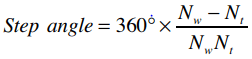
In Figure 5, Nw equals 8 and Nt equals 6. Therefore, the step angle can be computed as 360(2/48) = 15°. The angular resolution can be improved by increasing the number of windings and teeth. With the right structure, the step angle can be made much less than that of a PM stepper.
However, there’s a problem. The torque of a VR stepper is so low that it can’t turn a significant load. For this reason, VR steppers are not commonly found in practical systems. In fact, I’ve only ever seen a handful of VR motors for sale.
To make up for the shortcomings of VR steppers, engineers have designed a motor that combines the resolution of a VR motor and the torque of a PM motor. This is called a hybrid (HY) stepper.
Hybrid (HY) Steppers
A hybrid (HY) stepper provides the best of both worlds. Like a PM stepper, its rotor has magnets that provide torque. Like a VR stepper, the rotor has teeth that improve the angular resolution.
Hybrid motors have two disadvantages. First, HY steppers can be significantly more expensive than PM steppers. Second, HY steppers are larger and heavier than PM steppers. To see why this is the case, you need to understand their structure.
Structure: If you followed the discussions of PM and VR steppers, HY steppers won’t present any difficulty. Their rotors and stators are different from those of either stepper type, but the principle of their operation is similar.
Rotor: If you compare the HY stepper to the PM stepper, you’ll see that the HY stepper is longer. The reason for this is that the HY stepper rotor has (at least) two rotating mechanisms connected to one another. These are called rotor poles, and Figure 6 gives an idea of what they look like.
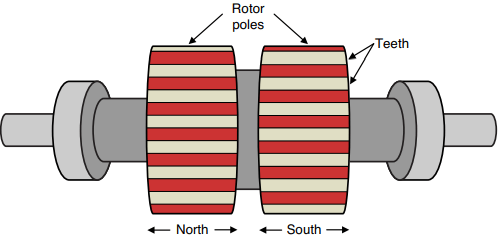
The rotor poles are magnetized so that one behaves like a north pole and one behaves like a south pole. Each pole has its own teeth, and the teeth of one rotor pole are oriented between those of the other. The angular difference between the two sets of teeth determines the step angle of the motor. The more teeth the stepper has, the better the angular resolution.
The rotor in Figure 6 has one pair of rotor poles, but other HY steppers may have two, three, or more pairs. Adding rotor poles increases the stepper’s rotational torque and holding torque, but also increases its size and weight.
Stator: The stator windings of a PM stepper or VR stepper are too large to attract/repel the teeth of one rotor pole without repelling or attracting the teeth of the other rotor pole. For this reason, the stator of an HY stepper has teeth that are approximately the same size as the teeth on the rotor. This is shown in Figure 7.
In this figure, each winding has three teeth. In a real stepper, the windings may have many more. If a winding is energized to produce a north pole, its teeth will attract the teeth of the rotor’s south pole. If a winding behaves as a south pole, its teeth will attract the teeth of the rotor’s north pole.
Operation: Like a VR stepper, an HY stepper can have multiple phases, one for each pair of windings. But the majority of the HY steppers I’ve encountered are like PM motors. That is, the windings are divided into two phases: A/A’ and B/B’. These are the phases labeled in Figure 7.
Each phase receives positive current, negative current, and zero current. When one phase is energized, its windings attract the teeth of one rotor pole. When the next phase is energized, its windings attract the teeth of the other rotor pole.
Hybrid steppers commonly have 50 – 60 teeth on a rotor pole, which increases the angular resolution. It’s common to see hybrid steppers with step angles as low as 1.8° and 0.9°.