Sizing the Battery Bank
After you know what your client’s electrical lifestyle is on an average day, you need to translate that into the amount of energy stored in her battery bank (also known as the battery bank’s capacity).
For any battery-based system — whether utility-interactive or stand-alone — when you size the battery bank, you take the view that no other source of power exists (at least for a certain amount of time) and that the battery bank is the primary source of energy (the PV array, a generator, or the util- ity merely replenishes the battery bank when it discharges).
Consequently, you need to size the battery bank to run the electrical loads your client wants, when she wants — which means you need to establish some criteria that you expect the battery bank to follow. All of the following dictate the battery bank capacity you’re looking for:
- The efficiency of the inverter
- The number of days you expect the battery bank to last without recharging
- The batteries’ operating temperature and voltage
- How much of the battery bank your client is willing to use
- The voltage at which you want the battery to operate
The next sections provide greater details on these variables. They also explain how to put them all together so you can accurately determine the battery capacity needed and create the battery bank.
When you buy batteries to make up the entire battery bank, you have a few options. The most common battery type for battery-based PV systems is a 6 V nominal battery. (This battery has three individual cells in it that are all wired internally to deliver 6 V across the terminals.) You then take these batteries and wire them in a series-parallel arrangement to achieve the voltage and capacity characteristics you’re after.
Other options include 12 V nominal batteries as well as individual 2 V cells in their own plastic cases; these cells look like batteries, but because there’s only one cell, technically they’re cells and not batteries. (Batteries also come in 4 V and 8 V nominal arrangements, although these are less common.)
Inverter efficiency
There’ll always be some losses associated with turning DC into AC, which is why no inverter can deliver 100 percent of the energy from a battery bank to the loads. However, if the inverter can be more efficient at inverting, the battery bank can be smaller.
Consider the AC loads attached to the proposed inverter and the inverter’s size (in terms of power output) in order to maximize efficiency levels. What I mean by this is don’t put in a 4 kW inverter if all the client will ever draw is 1 kW. Instead, try to match the loads and the inverter. (I explain inverter sizing in more detail later in this article.)
Inverter manufacturers list the efficiencies of their units on all of their spec sheets. What you need to remember is that the number listed by the manufacturers is the peak efficiency value. As such, it’ll almost always be an impressive value that’s somewhere near 95 percent. Although 95-percent efficiency may be possible, it’s not achievable on a frequent basis.
Most battery-based systems are regularly closer to 90-percent efficiency. Like all variables, this percentage will vary, but 90 percent is a fair value that represents a typical operating efficiency for an inverter.
The days of autonomy
The number of days your client wants her battery bank to sustain her electrical life style is known as the days of autonomy. In other words, it’s the number of days the client expects her battery bank to provide her with her average daily energy requirements without needing to be recharged by the PV array and the charge controller, generator, or utility.
This number is completely up to the system owner but you (as the system designer) should offer suggestions that will keep your client satis- fied. The local climate usually plays a major role in this decision, as does the available budget for the project. As you can imagine, the more days of autonomy, the more batteries you need and the higher the system cost climbs.
Many stand-alone residential applications use two or three days of autonomy as the starting point, whereas most utility-interactive systems use just a single day. For commercial applications, the grid is typically present, so one day of autonomy should suffice (although your commercial client may want more than that based on her business and the amount of lost revenue associated with a power outage).
You can consider adding more days of autonomy, but then you have to play a balancing game with the size of the battery bank and the size of the PV array (and your client’s checkbook). I explain how to size the PV array to the battery bank later in this article.
The temperature used for battery operation
The temperature that batteries operate at affects their capacity. The colder a battery is, the less capacity it can deliver. Why? Because the efficiency of the chemical reaction occurring inside the battery increases and decreases at different temperatures.
Battery manufactures publish the exact effects that temperature has on their batteries, so you should be able to find that data for the battery you’re considering in order to apply the correct temperature derate factor (the percentage of the capacity you can expect from a battery based on the temperature). I show you how to apply the temperature derate factor later in this article.
Because most systems use lead-acid batteries and the technology is pretty consistent among the different manufacturers, I use a single temperature derate factor: 90 percent. This percentage corresponds to a battery temperature of approximately 60 degrees Fahrenheit and indicates that at that temperature, the battery will only be able to deliver 90 percent of its rated value (the battery’s capacity at 77 degrees Fahrenheit).
The depth of discharge
Depth of discharge (DOD) is the amount of energy drawn from the battery bank; it’s generally given in terms of a percentage. The higher the DOD value, the more energy has left the battery bank. As with days of autonomy, DOD can (and should) be dictated in the system-design process because it affects the overall size of the battery bank.
When you look at a typical chart provided by battery manufacturers that shows the number of cycles versus DOD, it becomes apparent that the smaller the DOD is, the greater the number of cycles (a cycle is the period from when the batteries’ capacity is drawn down to when it’s recharged).
Although this fact probably isn’t surprising, it doesn’t mean you should try to baby the batteries and design a sys- tem around a small DOD. What you really need to do is evaluate where on the curve the maximum amount of energy will be delivered over the battery bank’s life.
To determine the ideal DOD to use with a battery bank, look at the whole picture in graph form; a graph shows a battery bank’s number of cycles against the percentage of its discharge. Figure 2 shows an example.
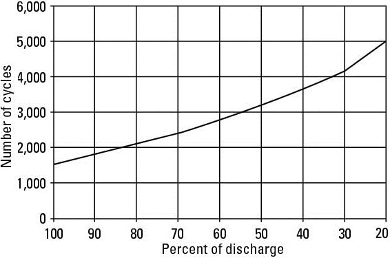
If the battery bank in Figure 2 is rated at 400 amp-hours (Ah), you can use that information to estimate the energy delivered over the course of the battery bank’s life.
From the graph in Figure 2, you can see that this battery bank will last for approximately 3,200 cycles if the DOD is only 50 percent. The number of cycles is reduced to approximately 2,100 when the DOD is 80 percent. So which DOD delivers more energy over the life of the battery bank? Run the numbers to figure it out:
400 Ah x 50% DOD per cycle x 3,200 cycles = 640,000 Ah 400 Ah x 80% DOD per cycle x 2,100 cycles = 672,000 Ah
Even though the idea of reducing the DOD looks good at first glance because it increases the overall life of the battery bank, it results in fewer amp-hours delivered. Because the battery bank’s job is to store and deliver energy, you may want to tell your client to consider discharging the batteries more often to maximize her investment (and reduce the system’s initial cost).
When evaluating the DOD, most battery bank designs use a value that’s some- where between 50 percent and 80 percent, but there’s really no exact “right” answer. You have to evaluate the options and make a suggestion based on the information in the charts from the manufacturer of the batteries you use in the bank.
Be careful to never exceed an 80-percent DOD in your design. Repeatedly reducing a battery bank’s capacity more than 80 percent harms the batteries and causes premature failure of the bank.
Nominal voltages
For any battery-based system you install, you need to look at battery bank nominal voltages of 12, 24, or 48 VDC. (Nominal voltage is a reference voltage) These voltages correspond to the inverter input requirements for the majority of commercially available inverters. It also corresponds to the nominal voltages of lead-acid battery cells, which are 2 V nominal.
Recently, battery-based systems have moved to higher voltages, which means that even modestly sized battery systems are commonly wired for 48 VDC. If you’re wiring a battery bank for a very small PV system (less than 200 W or so) or a system that’s using DC loads directly (such as recreational vehicles), you may consider wiring the batteries for only 12 V.
Systems using inverters that produce relatively small AC power levels (less than 2,000 W) may be able to justify using a 24 V battery bank, but with the advancements made in inverter and charge controller technologies, 48 V battery banks have become very popular. (Note that the wattage levels listed here are by no means absolute values. Rather, they’re common guidelines you can follow.
They represent the goal of keeping conductor [wire] sizes down by increasing voltages and reducing current values.)
Figuring out the battery capacity you need
At this point, you should’ve defined the variables needed to determine the overall battery bank capacity (if you haven’t, see the previous sections). Now you just need to apply them.
The easiest way to do that is to consider each variable individually, starting with the average daily energy consumption value you determined during your load analysis. If you follow the steps in this section, you can estimate the required capacity for a battery bank in both a utility-interactive and stand-alone system.
1. Determine the average daily AC watt-hours (or kilowatt-hours) consumption level.
I explain how to do this in the earlier “Determining the average daily energy consumption for stand-alone systems” section. For the purposes of providing an example, refer to Figure 1 to find that the average daily energy consumption of my sample client is 5,780 Wh, or 5.78 kWh.
2. Divide the watt-hours value from Step 1 by the estimated inverter efficiency.
This step increases the required capacity due to the fact that an inverter loses some of its stored capacity during the process of turning DC into AC (10 percent loss is common). Continuing with the example, you find that 5.78 kWh ÷ 0.9 = 6.42 kWh (90 percent is a fair inverter efficiency to estimate).
3. Add any energy consumption from DC loads to the watt-hours value in Step 2.
This value represents the total daily energy consumption for all the loads con- nected to the battery bank. If the client has three 20 W DC lights that she runs for two hours each day, the total DC energy consumption is 3 lights x 20 W x 2 hours = 120 Wh, or 0.12 kWh. The total energy consumption is therefore 6.42 kWh + 0.12 kWh = 6.54 kWh.
4. Multiply the energy value from Step 3 by the desired days of autonomy.
Doing so tells you the amount of energy the battery bank needs to store (two or three days is a pretty typical value). My example client has a stand-alone, battery-based system and wants three days of autonomy, so that makes the new energy value 6.54 kWh x 3 days = 19.62 kWh.
5. Divide the value calculated in Step 4 by the temperature compensation value provided by the battery manufacturer.
Ninety percent of manufacturers estimate the adjusted capacity at 60 degrees Fahrenheit. Apply the manufacturer’s value here for the estimated temperature of the battery bank you’re considering. So if the example battery bank will be stored at 60 degrees Fahrenheit, perform this calculation: 19.62 kWh ÷ 0.9 = 21.8 kWh.
6. Divide the value from Step 5 by the allowable depth of discharge.
The greater the DOD, the smaller the battery bank can be because you’ll be using more of the capacity (approximately 50 to 80 percent). This client and I settled on a DOD of 75 percent, so the math looks like this: 21.8 kWh ÷ 0.75 = 29.1 kWh.
7. Divide the value from Step 6 by your desired nominal voltage for the battery bank.
Batteries are rated in amp-hours, not watt-hours. By using the nominal battery bank voltage, you can determine the required amp-hours for the battery bank (use a 12 V, 24 V, or 48 V value here). The system in my running example will be installed at 48 V to keep the current values at a minimum and reduce the conductor sizes. Here’s the math: 29.1 kWh ÷ 48 V = 0.606 kAh, or 606 Ah.
Strung along: Wiring the battery bank
As soon as you know what the capacity of the battery bank should be and the nominal voltage, you’re ready to evaluate the different battery options and decide which one is best for the battery bank you’re constructing.
When wiring batteries into a battery bank, you need to consider the voltage of each individual battery as well as each battery’s capacity because you’re creating a string of batteries by placing multiple batteries in series.
As you make the series connections, the voltage will increase while the capacity (measured in amp-hours) remains constant. To increase the capacity of the bank, you must place more strings in parallel with the first in order to keep the voltage constant while increasing the capacity.
If you install a single string of batteries in series and in a few years your client has an issue with any one battery (or cell), the system will likely need to be shut down until that one battery is replaced. That may seem extreme, but when you have a single string, the electrons have to flow through each battery to complete the circuit. If one battery is dead or shorted, the current can’t get past that battery.
This fact is why many PV pros regard placing two strings in parallel as a more desirable solution. With two strings in parallel, you can keep all the parallel connections equal in length and the battery bank as a whole can perform well. If any one battery or cell peters out, you can just remove one string from the bank, allowing the system to continue limping along until the situation is corrected.
As much as possible, avoid placing more than two strings in parallel. As soon as you begin placing three or more strings in parallel, it becomes increasingly difficult to keep the parallel conductors’ resistance equal. The individual strings have the tendency to charge and discharge at different rates, causing imbalances in the bank and reducing the overall life of the batteries.
To determine the specifications for the batteries, I like to first look at the required capacity of the battery bank. Because you want to wire the battery bank with either one or two strings of batteries, you need to find a battery with a capacity amount equal to or half of the capacity you calculated in the preceding section. When you have an idea of the battery capacity needed, you can evaluate different battery spec sheets to decide on the battery for your system.
Find the batteries with the correct capacity first and then look at how many you need based on your nominal voltages. When you’re evaluating battery specifications, use the C/20 capacity value reported by the battery manufacturer. The C/20 rate is a good value to use unless you know that your discharge rate will be something dramatically different.
To determine the number of batteries required in a string, divide the nominal battery bank voltage by the individual batteries’ nominal voltages. From the example in the last section, I calculated that the battery bank would need to have a capacity of 606 Ah at 48 V. And because I want to have two strings of batteries in my bank, I need to look for a battery that has a C/20 rate of 303 Ah (which is difficult to find, so I may need to settle on a battery with a C/20 rate of 300 Ah or buy into a bigger 350 Ah battery). Batteries with this level of capacity are commonly found in 6 V nominal options.
So if you’re going to wire a bank for 48 V and each battery is 6 V, you know the battery strings should be eight batteries long. Here’s the math: 48 V ÷ 6 V = 8 batteries per string
Sizing the PV Array
When it comes to sizing the PV array in a battery-based system, a number of considerations are required. This is one area where the type of system — utility- interactive or stand-alone — makes a big difference in your approach.
For utility-interactive systems, the PV array generally operates more like it does in grid-direct systems; the utility is present most of the time, and the inverter sends excess power into the grid to run the meter backward.
The major difference between utility-interactive, battery-based systems and grid- direct systems is that in the former system, a battery bank is ready to power any loads on the backup load panel.
Consequently, the PV array’s primary responsibility is to produce as much power as possible at all times to offset loads and send energy back into the grid. For stand-alone systems, the actual performance of the PV array in relation to the battery bank is more important because the array is the primary source of power and the primary battery charger.
The owner of this type of system may be willing to adjust the tilt of her array seasonally to optimize for the sun’s position in the sky with the goal of maximizing performance and minimizing generator run time.
Sizing the array in a utility-interactive system
If a battery-based PV system will be used simply to back up a few loads for a home or business that’s connected to the utility grid (in other words, the system is utility-interactive), the process of sizing the array works similarly to the process of sizing an array for a grid-direct system (see previous article). Of course, any system that’s connected to the utility requires interconnection agreements.
In a utility-interactive, battery-based system, the batteries spend the majority of their lives full and waiting to go to work during a utility outage. Also, the battery bank is typically sized to last the duration of the outage, which means the PV array isn’t used as a daily battery charger. Instead, it’s merely used to reduce the power required by the utility (and, if the system owner is lucky, send power back into the grid).
Given this fact, you should size the PV array in a utility-interactive, battery-based system based on the client’s available budget, the area available for the array, and the annual energy consumption.
Sizing the array in a stand-alone system When the battery-based system you’re sizing is of the stand-alone variety, the PV array needs to produce an amount of energy equal to your client’s average daily energy consumption (as calculated in the earlier “Determining the average daily energy consumption for stand-alone systems” section); if it doesn’t, the battery bank will never be able to recharge fully.
In addition, the array should be able to help recharge the battery bank after there has been little to no charging by any source (such as the PV array or a generator) and the battery bank has dipped into the reserve supplied by your client’s desired days of autonomy.
In reality, the amount of energy consumed isn’t a constant value; it changes throughout the year. Typically, people use more energy during the winter, which happens to correspond to the time of year with the lowest solar resource (if your client has large cooling loads, such as air conditioners, this may be different).
This situation presents a problem for you as a PV system designer. If you design the PV array around the scenario of high consumption and low solar resource, you’ll end up with a PV array that’s very large. Come summertime, when the energy consumption is reduced and the solar resource is increased, the PV array will be oversized and have the batteries charged very early in the day, which is bad because the PV array will be underutilized those times of the year, and the initial system cost will be outrageous.
To determine the appropriate array size in watts, you need to gather some infor- mation about the site and make some assumptions regarding the operation of the system. These values will help you estimate the array size needed based off of the total energy consumption you calculated in the very beginning of the process.
Examining efficiency values
For the array to produce enough energy for the loads, you need to look at the losses within the system. This means considering two main efficiency values: the batteries’ charging and discharging efficiency and the efficiency of the PV array to deliver the energy. These values vary, but you can use the following estimations, which are based on typical equipment and technologies:
Battery efficiency: A common value for battery efficiency is 85 percent, which represents the fact that you can never get 100 percent of the energy used to charge the battery when discharging the battery. This efficiency value represents losses internal to the battery as well as the ability for the charge controller to charge the battery.
PV array efficiency: This value is affected by, among other things, the temperature of the array, how dirty the modules are, voltage losses in the wiring, and the age of the array. You can look at all the individual losses and estimate their effect on the total array, but I prefer to estimate the average value at 75 percent.
This percentage is on the conservative side in terms of esti- mating the losses, but for a stand-alone situation, this approach allows you to supply all the energy required more often.
Considering the total available solar resource
Another consideration you must make is the total solar resource factor (TSRF), which is a combination of shading effects and the effects of the array’s tilt and azimuth. You determine what this value is when you conduct the site survey.
Settling on a number of peak sun hours
Most off-grid clients who want a stand-alone system quickly come to the realization that they’ll need to use a generator part of the time. Your goal when designing a stand-alone, battery-based system for them is to minimize that run time. Consequently, you need to choose a certain number of peak sun hours for your design.
The addition of an external charging source, like a generator, allows you more flexibility with the solar resource data. When designing an array for an off-grid system that has a generator, I typically use the average number of peak sun hours for the site.
If, however, your client doesn’t want a generator, you need to design the system based on the lowest amount of solar resource, which is typically the value found in the middle of winter.
Running the numbers
After you define the variables related to array sizing, you’re ready to estimate the PV array size in watts. Use the following steps:
1. Gather the total energy value calculated in the load analysis.
This is the same total energy value you used when sizing the battery bank (see the earlier “Figuring out the battery capacity you need” section). In that example, the total energy consumption (of both AC and DC loads) was 6.54 kWh.
2. Multiply the estimated battery and PV array efficiencies.
Based on what I tell you in the earlier “Examining efficiency values” section, take 85% × 75% to get 64%. Even if you choose not to use these numbers, what you wind up with after completing this step is the total efficiency of the PV array in charging the batteries.
3. Multiply the efficiency value from Step 2 by the TSRF that you determined during the site survey.
The client in this example has a TSRF of 90 percent (in other words, she loses 10 percent of the potential resource due to shading and the array tilt and orientation). Here’s the calculation: 0.64 x 0.9 = 0.57.
4. Divide the total energy value found in Step 1 by the total efficiency value found in Step 3.
Doing so gives you the total daily amount of energy the array needs to produce. In this case, that’s 6.54 kWh ÷ 0.57 = 11.5 kWh.
5. Divide the energy value from Step 4 by the peak sun hours value you decided to use. The result of this equation is the array size in watts.
So if the average peak sun hours is 4.2 for the client’s site, then the array needs to produce 11.5 kWh in 4.2 hours, or 11.5 kWh ÷ 4.2 = 2.73 kW = 2,730 W.
The array size you calculate by using the preceding steps is the size needed to produce the amount of energy consumed on an average day with an average amount of solar resource available. The actual performance of the system once installed will vary over the different seasons.
When you know the appropriate array size in watts, you can calculate the number of modules needed. Divide your previously calculated array wattage by the standard test conditions (STC) rating of the modules you want to use.
For example, if the module you want to use is rated at 195 W, you can divide 2,730 W by 195 W to find that you need 14 modules. (Note: More often than not, this calculation doesn’t result in a whole number. You need to round up to the next whole number and oversize the array a bit. Don’t worry; you’re better off designing a system that will produce more energy than not enough.)
Sizing the Charge Controller
After you size the battery bank and PV array, your next step is to size the charge controller. For both types of battery-based systems, the most common controller choice is the maximum power point tracking (MPPT) controller, although you can also use a pulse-width modulation (PWM) controller. The sections that follow walk you through the steps of sizing a charge controller for any battery-based system.
As with inverters in grid-direct systems, the charge controller connected to the PV array in a battery-based system needs to be large enough to handle all the power provided by the array. Consequently, you may end up with multiple charge controllers in your system.
Each charge controller is connected to a dedicated PV array, but they all connect to the same battery bank. (I walk you through the process of determining how many charge controllers to specify [select] in the following sections.)
Voltage specifications
All charge controllers have a voltage window that you must stay within. Specifically, they have a maximum input voltage that they can accept and a minimum voltage value that they need to stay above. Your job is to look at the temperature- adjusted voltages from the PV modules to correctly account for the charge controller’s window. You evaluate the voltage window for charge controllers the same way you do for inverters (see privious article).
When you know the temperature-adjusted voltages for the PV modules, you can use the number and type of modules you decided on (see the earlier “Running the numbers” section if you haven’t yet) to figure out the number of modules you can place in series for each string. Just like with inverters, all the strings connected to the same charge controller must be the same length.
But unlike grid-direct inverters, the charge controller in a battery- based system usually operates at a much lower voltage. You therefore have to use fewer modules per string. For example, it’s common to see strings of just three or four modules connected to a charge controller; in a grid-direct system, you say see a string of eight to ten modules running a grid-direct inverter.
After you know how many modules are in each string, you can determine how many strings to place in parallel based on the power require- ments for the desired PV array and finalize the charge controller specifi- cation by looking at the amperage requirements (see the next section).
After you determine the required voltage window based on the PV array you’re using, you can narrow down your choice of charge controller a bit by looking at the relationship between a PV array’s voltage and a battery bank’s voltage. This is another area where the difference between MPPT and PWM controllers makes it- self known.
Most, but not all, MPPT controllers have the ability to take a higher voltage on the input side (the PV array) and reduce that voltage to a smaller amount on the output side (the battery bank). By using MPPT controllers that have the ability to step down the array voltage, you give yourself more design options and open up the possibility of using a greater number of PV modules. (On a charge controller without this feature, the voltage window is extremely narrow, so you’re forced to use a PV module (or string of modules) that has the same nominal voltage as the battery bank.)
Also, by wiring the array at a “high” voltage, you can reduce the size of the wires running between the array and the controller. (To deliver the same amount of power, a higher-voltage array needs to push less current through the conductors, and the amount of current flowing through directly affects conductor sizing.)
You also get the benefit of using modules that have been manufactured with voltages that don’t correspond to traditional battery-charging voltages, which opens up your choice of modules even more.
Many PV manufacturers now make their modules with the grid-direct market in mind, which means their modules can’t be connected to a PWM controller and effectively charge a battery.
If you try to use a grid-direct style module with a PWM controller, you’ll end up with either a PV module that doesn’t have enough voltage to push the current into the battery or too much voltage that may damage the controller. A PWM controller, unlike an MPPT controller, needs the PV array nominal voltage equal to the battery bank’s nominal voltage.
When looking at the voltage specifications for a PWM controller, you really don’t need to go through the trouble of adjusting the module voltages for temperature and then comparing that to the controller’s voltage window. Because the nominal input must equal the nominal output, this work has essentially been done for you.
The downside is that this convenience means you can’t use just any old module you want for your system. You must use modules that have been manufactured specifically as 12 V or 24 V nominal and wire them in series as required by the battery bank.
Essentially, the features of MPPT charge controllers make it easy to justify the added expense of one when looking at PV systems with large arrays meant to provide the energy for a home or small commercial building. The main benefit of an MPPT controller, compared to a PWM controller, is the ability to use the full power output of the PV array regardless of the batteries’ charging voltage.
In other words, you can get closer to the full benefit of the array’s power, which equates to more efficient battery charging.
Power or amperage specifications
In addition to voltage specifications, the other half of charge controller sizing is the power or current specifications. You need to consider these limitations when sizing a controller to make sure you get the full benefit of the controller.
Depending on the charge controller technology used, you have to look at either the power or the current values from the PV array. Note: After completing the math described in the next sections, you may end up with a final PV array size that’s different from what you calculated earlier. The number of modules per string and the number of strings may dictate that you adjust the array size.
Some simple math: PWM charge controllers
For PWM controllers (or for MPPT controllers that use a PV array nominal voltage equal to the battery bank’s nominal voltage), determining the current specifications is easy as long as you know the specifics for the PV array.
For example, if you’re using a PV module that has a nominal voltage of 24 V and the battery is wired for 48 V, the modules will be wired with two in each string. If you have five strings in parallel, you can calculate that the maximum power current, Imp, for that array will be the individual modules’ Imp value times 5.
With a PWM controller, the current rating of the controller must be at least that much current. For example, if the 24 V nominal PV module being used has a Imp value of 6 A and 5 strings are in parallel, the total current output from the array will be 5 strings × 6 A = 30 A. So the PWM controller should have a minimum operating current rating of 30 A.
For safety, you should always verify that the charge controller can handle the short circuit current from that same configuration by multiplying the module’s Isc value by the number of strings in parallel and comparing the result to the controller’s maximum short circuit current input value.
A little tougher: MPPT charge controllers
When you’re working with an MPPT controller and you want to step down the array’s voltage to a lower value, figuring out the current specifications becomes slightly more difficult.
In this situation, you’re mainly concerned with the current value leaving the controller. You need to make sure you don’t apply too much power to the controller and try to push more current out of the controller than its rating.
If you do, then the controller will current limit itself (send out a certain amount of current even though there’s more available from the array) and the “extra” power will be turned into heat. This situation won’t damage the controller, but it isn’t ideal. To guarantee that you don’t exceed the charge controller’s abilities, relate the controller’s limitations based on its output current and the battery bank voltage.
If you multiply the controller’s maximum output current value by the battery bank’s nominal voltage, you get a certain number of watts, which is a power value that you can then relate directly to the PV array’s size. How so? Well, you want to make sure that the PV array doesn’t exceed this wattage value, or else you run the risk of applying too much power to the controller and creating too much heat.
Consider this example. A common MPPT charge controller has a current output value of 60 A. If you want to use an MPPT controller to charge a 24 V nominal battery bank from a PV array, you need to ensure that the array doesn’t exceed 24 V x 60 A = 1,440 W. By keeping the array below this power value, the controller can take all the available voltage and current from the array and effectively push that into the battery bank.
If in this calculation you find that the controller’s power value is less than the PV array size you calculated, you can either look for a controller with a larger current output value or buy multiple controllers and wire the PV array into subarrays so that each subarray’s power doesn’t exceed the controller’s limits.
A check before you move on: Comparing the array size to the battery capacity
After you finish sizing the charge controller but before you go too much further, you should check that the PV array’s power output and the battery bank’s capacity are sized within reason. What you’re concerned with here is the PV array’s charging ability as compared to the battery bank’s capacity. You want the PV array’s charging ability to be somewhere between a C/10 rate and a C/20 rate (the number listed represents the hours needed to charge the battery bank).
If the PV array is too large (above the C/10 rate), it’ll charge the battery bank too fast, and the batteries won’t be able to charge efficiently because they won’t be able to take all the current sent by the array. If the PV array is too small (below the C/20 rate), the charge rate will be small, and the PV array will never be able to fully recharge the battery bank.
To determine where you stand, use the battery bank’s capacity and figure out what the C/10 and C/20 values are. Your PV array’s charging current (the output of the charge controller) should be somewhere between those two numbers. (Note: The slower C/20 rate is typically more realistic due to budget and space restraints.)
Here’s an example to help you see what I mean: If you have a 600 Ah battery bank, you want the charging current from the PV array to land somewhere between 60 A and 30 A (600 Ah ÷ 10 hours = 60 A and 600 Ah ÷ 20 hours = 30 A). If the battery bank is at 48 V nominal, then the PV array would be between 1,440 W and 2,880 W in size.