DC Motor Speed Control Using PWM
DC motors exhibit the following relationships between mechanical and electrical quantities:
Torque:
- Torque is directly proportional to armature magnetic field strength, which in turn is directly proportional to current through the armature windings.
- Torque is also directly proportional to the stationary pole magnetic field strength, which in turn is directly proportional to current through the field windings (in a motor with non-permanent field magnets)
Speed:
- Speed is limited by the counter-EMF generated by the armature as it spins through the stationary magnetic field. This counter-EMF is directly proportional to armature speed, and also directly proportional to stationary pole magnetic field strength (which is directly proportional to field winding current in a motor that is not permanent-magnet).
- Thus, speed is directly proportional to armature voltage
- Speed is also inversely proportional to stationary magnetic field strength, which is directly proportional to current through the field windings (in a motor with non-permanent field magnets).
A very simple method for controlling the speed and torque characteristics of a wound-field (nonpermanent magnet) DC motor is to control the amount of current through the field winding:
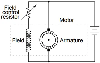
Decreasing the field control resistor’s resistance allows more current through the field winding, strengthening its magnetic field. This will have two effects on the motor’s operation:
- first, the motor will generate more torque than it did before (for the same amount of armature current) because there is now a stronger magnetic field for the armature to react against;
- second, the motor’s speed will decrease because more counter-EMF will be generated by the spinning armature for the same rotational speed, and this counter-EMF naturally attempts to equalize with the applied DC source voltage.
Conversely, we may increase a DC motor’s speed (and reduce its torque output) by increasing the field control resistor’s resistance, weakening the stationary magnetic field through which the armature spins.
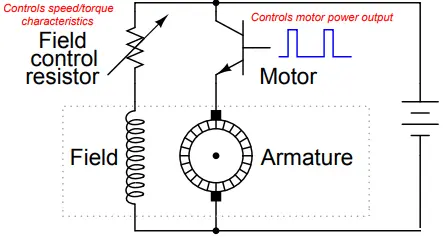
Regulating field current may alter the balance between speed and torque, but it does little to control total motor power.
In order to control the power output of a DC motor, we must also regulate armature voltage and current. Variable resistors may also be used for this task, but this is generally frowned upon in modern times because of the wasted power.
DC Motor Speed Control Using PWM
A better solution is to have an electronic power control circuit very rapidly switch transistors on and off, switching power to the motor armature. This is called pulse-width modulation, or PWM.
The duty cycle (on time versus on + off time) of the pulse waveform will determine the fraction of total power delivered to the motor:
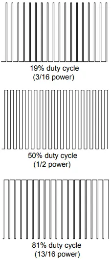
Such an electronic power-control circuit is generally referred to as a drive. Thus, a variable-speed drive or VSD is a high-power circuit used to control the speed of a DC motor.
Motor drives may be manually set to run a motor at a set speed, or accept an electronic control signal to vary the motor speed in the same manner an electronic signal commands a control valve to move.
When equipped with remote control signaling, a motor drive functions just like any other final control element: following the command of a process controller in order to stabilize some process variable at setpoint.
A DC motor drive that simply varied power to the motor according to a control signal would be crude and difficult to apply to the control of most processes.
Necessity of Tachogenerator
What is ideally desired from a variable-speed drive is precise command over the motor’s speed.
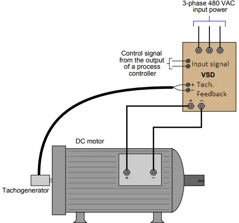
For this reason, most VSDs are designed to receive feedback from a tachometer mechanically connected to the motor shaft, so the VSD “knows” how fast the motor is turning.
The tachometer is typically a small DC generator, producing a DC voltage directly proportional to its shaft speed (0 to 10 volts is a common scale). With this information, the VSD may throttle electrical power to the motor as necessary to achieve whatever speed is being commanded by the control signal.
Having a speed-control feedback loop built into the drive makes the VSD a “slave controller” in a cascade control system, the drive receiving a speed set-point signal from whatever process controller is sending an output signal to it:
The integrity of the tachogenerator feedback signal to the VSD is extremely important for safety reasons. If the tachogenerator becomes disconnected – whether mechanically or electrically (it doesn’t matter) – from the drive, the drive will “think” the motor is not turning.
In its capacity as a speed controller, the drive will then send full power to the DC motor in an attempt to get it up to speed. Thus, loss of tachogenerator feedback causes the motor to immediately “run away” to full speed. This is undesirable at best, and likely dangerous in some cases.
Elimination of RFI Noise
As with all forms of electric power control based on pulse durations and duty cycles, there is a lot of electrical “noise” broadcast by VSD circuits.
Square-edged pulse waveforms created by the rapid on-and-off switching of the semiconductor power devices are equivalent to infinite series of high-frequency sine waves, some of which may be of high enough frequency to self-propagate through space as electromagnetic waves.
This radio-frequency interference or RFI may be quite severe given the high power levels of industrial motor drive circuits. For this reason, it is imperative that neither the motor power conductors nor the conductors feeding AC power to the drive circuit be routed anywhere near small-signal or control wiring, because the induced noise will wreak havoc with whatever systems utilize those low-level signals.
RFI noise on the AC power conductors may be reduced by routing the AC power through lowpass filter circuits called line reactors placed near the drive.
These line reactors, consisting of ferrous metal core inductors wired in series with the drive, block high-frequency noise from propagating back to the rest of the AC power distribution wiring where it may influence other electronic equipment.
However, there is little that may be done about the RFI noise between the drive and the motor other than to shield the conductors inside of well-grounded metallic conduit and/or to use grounded-shield power cables.