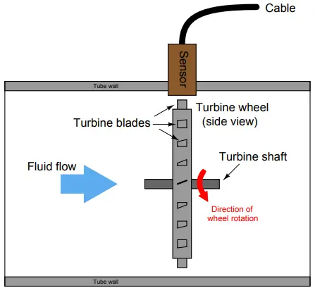
Turbine Flowmeters
Turbine flowmeters use a free-spinning turbine wheel to measure fluid velocity, much like a miniature windmill installed in the flow stream. The fundamental design goal of a turbine flowmeter is to make the turbine element as free-spinning as possible, so no torque will be required to sustain the turbine’s rotation.
If this goal is achieved, the turbine blades will achieve a rotating (tip) velocity directly proportional to the linear velocity of the fluid, whether that fluid is a gas or a liquid:
The mathematical relationship between fluid velocity and turbine tip velocity – assuming frictionless conditions – is a ratio defined by the tangent of the turbine blade angle:
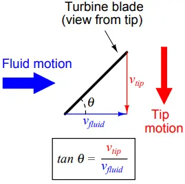
For a 45o blade angle, the relationship is 1:1, with tip velocity equaling fluid velocity. Smaller blade angles (each blade closer to parallel with the fluid velocity vector) result in the tip velocity being a fractional proportion of fluid velocity.
Turbine tip velocity is quite easy to sense using a magnetic sensor, generating a voltage pulse each time one of the ferromagnetic turbine blades passes by.
Traditionally, this sensor is nothing more than a coil of wire in proximity to a stationary magnet, called a pickup coil or pickoff coil because it “picks” (senses) the passing of the turbine blades.
Magnetic flux through the coil’s center increases and decreases as the passing of the steel turbine blades presents a varying reluctance (“resistance” to magnetic flux), causing voltage pulses equal in frequency to the number of blades passing by each second. It is the frequency of this signal that represents fluid velocity, and therefore volumetric flow rate.
A cut-away demonstration model of a turbine flowmeter is shown in the following photograph. The blade sensor may be seen protruding from the top of the flowtube, just above the turbine wheel:
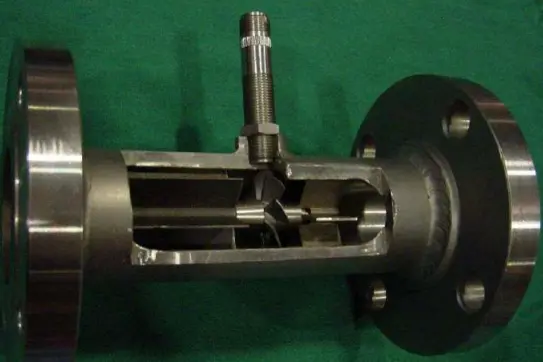
Note the sets of “flow conditioner” vanes immediately before and after the turbine wheel in the photograph.
As one might expect, turbine flowmeters are very sensitive to swirl in the process fluid flowstream. In order to achieve high accuracy, the flow profile must not be swirling in the vicinity of the turbine, lest the turbine wheel spin faster or slower than it should to represent the velocity of a straight-flowing fluid.
A minimum straight-pipe length of 20 pipe diameters upstream and 5 pipe diameters downstream is typical for turbine flowmeters in order to dissipate swirl from piping disturbances.
Mechanical gears and rotating cables have also been historically used to link a turbine flowmeter’s turbine wheel to indicators. These designs suffer from greater friction than electronic (“pickup coil”) designs, potentially resulting in more measurement error (less flow indicated than there actually is, because the turbine wheel is slowed by friction).
One advantage of mechanical turbine flowmeters, though, is the ability to maintain a running total of gas usage by turning a simple odometer-style totalizer. This design is often used when the purpose of the flowmeter is to track total fuel gas consumption (e.g. natural gas used by a commercial or industrial facility) for billing.
In an electronic turbine flowmeter, volumetric flow is directly and linearly proportional to pickup coil output frequency. We may express this relationship in the form of an equation: f = kQ
Where, f = frequency of output signal (Hz, equivalent to pulses per second), Q = volumetric flow rate (e.g. gallons per second), k = “K” factor of the turbine element (e.g. pulses per gallon).
Dimensional analysis confirms the validity of this equation. Using units of GPS (gallons per second) and pulses per gallon, we see that the product of these two quantities is indeed pulses per second (equivalent to cycles per second, or Hz):
[Pulses/s] = [Pulses/gal] [gal/s]
Using algebra to solve for flow (Q), we see that it is the quotient of frequency and k factor that yields a volumetric flow rate for a turbine flowmeter: Q = f/k
The inherent linearity of a turbine flowmeter is a tremendous advantage over nonlinear flow elements such as venturi tubes and orifice plates because this linearity results in a much greater turndown ratio for accurate flow measurement.
Contrasted against common orifice-type meters which are usually limited to turndown ratios of 4:1 at best, turbine meters commonly exceed turndown ratios of 10:1.
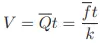
If pickup signal frequency directly represents volumetric flow rate, then the total number of pulses accumulated in any given time span will represent the amount of fluid volume (V ) passed through the turbine meter over that same time span. We may express this algebraically as the product of average flow rate, average frequency, k factor, and time:
A more sophisticated way of calculating total volume passed through a turbine meter requires calculus, representing change in volume as the time-integral of instantaneous signal frequency and k factor over a period of time from t = 0 to t = T:
We may achieve approximately the same result simply by using a digital counter circuit to totalize pulses output by the pickup coil and a microprocessor to calculate volume in whatever unit of measurement we deem appropriate.
As with the orifice plate flow element, standards have been drafted for the use of turbine flowmeters as precision measuring instruments in gas flow applications, particularly the custody transfer of natural gas.
Pressure and temperature compensation is relevant to turbine flowmeters in gas flow applications because the density of the gas is a strong function of both pressure and temperature.
The turbine wheel itself only senses gas velocity, and so these other factors must be taken into consideration to accurately calculate mass flow (or standard volumetric flow; e.g. SCFM). In high-accuracy applications, it is important to individually determine the k factor for a turbine flowmeter’s calibration.
Manufacturing variations from flowmeter to flowmeter make precise duplication of k factor challenging, and so a flowmeter destined for high-accuracy measurement should be tested against a “flow prover” in a calibration laboratory to empirically determine its k factor.
If possible, the best way to test the flowmeter’s k factor is to connect the prover to the meter on site where it will be used. This way, the any effects due to the piping before and after the flowmeter will be incorporated in the measured k factor.
Less-critical gas flow measurement applications may use a “compensated” turbine flowmeter that mechanically performs the same pressure- and temperature-compensation functions on turbine speed to achieve true gas flow measurement.
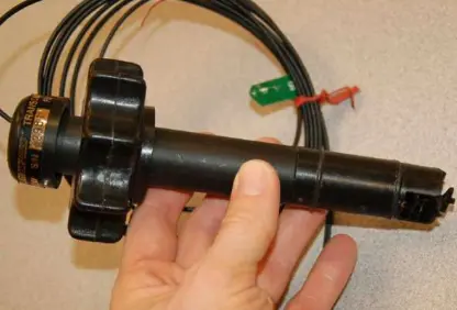
A variation on the theme of turbine flow measurement is the paddlewheel flowmeter, a very inexpensive technology usually implemented in the form of an insertion-type sensor.
In this instrument, a small wheel equipped with “paddles” parallel to the shaft is inserted in the flowstream, with half the wheel shrouded from the flow. A photograph of a plastic paddlewheel flowmeter appears here:
A surprisingly sophisticated method of “pickup” for the plastic paddlewheel shown in the photograph uses fiber-optic cables to send and receive light. One cable sends a beam of light to the edge of the paddlewheel, and the other cable receives light on the other side of the paddlewheel.
As the paddlewheel turns, the paddles alternately block and pass the light beam, resulting in a pulsed light beam at the receiving cable. The frequency of this pulsing is, of course, directly proportional to volumetric flow rate.
The external ends of the two fiber optic cables appear in this next photograph, ready to connect to a light source and light pulse sensor to convert the paddlewheel’s motion into an electronic signal:

A problem common to all turbine flowmeters is that of the turbine “coasting” when the fluid flow suddenly stops. This is more often a problem in batch processes than continuous processes, where the fluid flow is regularly turned on and shut off.
This problem may be minimized by configuring the measurement system to ignore turbine flowmeter signals any time the automatic shutoff valve reaches the “shut” position. This way, when the shutoff valve closes and fluid flow immediately halts, any coasting of the turbine wheel will be irrelevant.
In processes where the fluid flow happens to pulse for reasons other than the control system opening and shutting automatic valves, this problem is more severe.
Another problem common to all turbine flowmeters is lubrication of the turbine bearings. Frictionless motion of the turbine wheel is essential for accurate flow measurement, which is a daunting design goal for the flowmeter manufacturing engineers.
The problem is not as severe in applications where the process fluid is naturally lubricating (e.g. diesel fuel), but in applications such as natural gas flow where the fluid provides no lubrication to the turbine bearings, external lubrication must be supplied.
This is often a regular maintenance task for instrument technicians: using a hand pump to inject light-weight “turbine oil” into the bearing assemblies of turbine flowmeters used in gas service.
Process fluid viscosity is another source of friction for the turbine wheel. Fluids with high viscosity (e.g. heavy oils) will tend to slow down the turbine’s rotation even if the turbine rotates on frictionless bearings.
This effect is especially pronounced at low flow rates, which leads to a minimum linear flow rating for the flowmeter: a flowrate below which it refuses to register proportionately to fluid flow rate.