Encoders are non-contact, optical-based digital devices that are used for measuring displacement. They can be used to measure both linear and rotary displacement. We will concentrate on rotary-type encoders, which are widely used in motion-control applications.
Rotary encoders are available as incremental or absolute type. An incremental encoder measures changes in rotation from some datum position, while an absolute encoder measures the actual angular position.
When an incremental encoder is used, the motion system needs to be ‘homed’ to establish reference information. In its basic form, an incremental encoder is constructed from two light sources that shine light through a disk that has an alternating pattern of black and clear stripes.
The light is sensed by two photodetector sensors that are located on the other side of the disk.
Incremental Encoder Working Principle
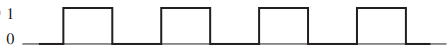
To understand the operation of an incremental encoder, let us assume first that we have only one light source and one sensor.
When the disk rotates, the light signal (as measured by the photo detector sensor) looks like that shown in Figure 1. The output of the sensor will be a train of pulses with each pulse corresponding to the light pattern that is captured by the optical sensor while one strip on the disk passes through the light sensor zone.
light/sensor combination.
To get angular displacement information, we simply count the number of pulses generated as the disk rotates from one position to another. Unfortunately, this simple scheme cannot provide us with direction information.
To get direction information, incremental encoders have another light source and sensor (called channel B). The channel B sensor is located one-half slot-width apart from the first sensor and photodetector (channel A). There are two ways to implement this offset in practice.
- There is only one track of lines: one light source-sensor combination is located to line up with the edge of one of the slots, while the other light sourcesensor combination is located to have an offset of one half-slot with respect to the edge of one of the slots.
- Two concentric tracks of lines are used: the slots in one track have an offset of one-half slot with respect to the slots in the other track, but the sensors have no offset between them.
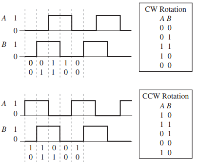
The pattern of the two sensor signals generated for clockwise (CW) and counterclockwise (CCW) rotations of a disk under constant angular speed are shown in Figure 2.
incremental encoder.
Notice how the B signal leads the channel A signal by a quarter of a cycle for CW rotation, and how it lags behind the channel A signal by the same amount for CCW rotation. The cycle that we are referring to is the chord distance made up of one black strip and one clear strip. This lead/lag between the two channel outputs enables one to determine the direction of the rotation of the shaft that is attached to the encoder disk.
To understand this further, examine the A and B channel signal patterns for CW and CCW rotations that are shown in Figure 2. Notice that the output switches between one of four possible states for either rotation direction, and the order of these states is different for each direction.
For example, if the photodetector sensors output is 00, then the next state will be 10 for CCW rotation and 01 for CW rotation. The different transitions for CW and CCW rotations enable one to write state-transition logic to determine the direction of rotation.
for an incremental encoder.
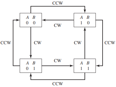
Figure 3 shows an example of a state-transition diagram that can do this job. Notice that, regardless of what state the output of the two sensors starts at, the diagram can determine the direction of rotation by examining the transitions from any one of the four possible states.
As noted before with the use of two sensors, we get four distinct states for each strip on the disk. Thus, if an encoder has 1000 strips (or lines), we will get 4000 distinct states per one revolution of the encoder disk. Thus, the use of two sensors improves the resolution of the encoder by a factor of 4, since we can count 4000 leading and trailing edges per one revolution compared to counting 1000 pulses per revolution for a single sensor. An encoder that gives four times the number of lines is operating in quadrature mode.
In practice, the number of counts per second can get very large. For example, if the 1000-line encoder was rotating at 1000 rpm, then we will get 66.6e3 counts per second if the encoder was operating in quadrature mode.
Most PC’s or microcontrollers cannot keep up with counting at this rate if the output from the A and B channels is directly connected to the digital input port of the PC/microcontroller. In practice, hardware counters are used to process the A and B signals instead of using a software counting solution. These dedicated counters implement logic very similar to the method shown in Figure 3.
The counter value is incremented by 1 on each state transition if the motion happens to be in one direction and is decremented by 1 for a motion in the opposite direction. To get the current position information, the PC or the microcontroller simply reads the output of the hardware counter. Thus, the processor does not have to worry about accuracy problems resulting from failing to count a particular transition.
Figure 4 shows an example of a commercial counter IC. The LS7166 IC is a 24-bit counter that can count in different modes, including up/down and quadrature.
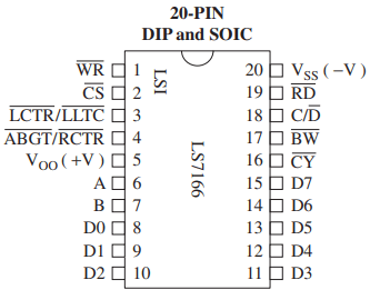
(Courtesy of LSI Computer
Systems, Melville, NY)
The incremental encoder A and B lines are connected to the A and B pins on this IC. This counter uses an 8-bit (pins D0 through D7) three-state I/O bus to communicate with external circuits. An 8-bit bus is used instead of a 24-bit to reduce the number of wires needed but also to be compatible with most microcontrollers/external devices, which have a limited number of I/O lines.
An external device can read the counter value by simply sending a preset control value over the I/O bus. This causes the 24-bit counter value to be transferred to the output port of the counter or the output latch. The three byte contents of the output latch are then transferred by performing three successive read operations of the output latch where (after each byte is read) the address pointer for the next byte is automatically incremented.
While incremental encoders do not have the limitations of potentiometers in terms of limited motion range and friction due to contact, they need to be ‘homed’ before they can be used in a motion-control application.
In homing, the motor is rotated in one direction until a reference signal changes state. The output of the counter is recorded at this location, and displacements are measured with respect to this reference counter or home position.
Most commercial incremental encoders have a third output called the marker or z-channel that is used in the homing sequence. A limitation of incremental encoders is that homing may not be safe to perform at all times.
An example would be a robot arm that uses incremental encoders and is used for operations inside a vehicle frame or in regions with obstacles. If the robot happens to lose power while it is inside the vehicle, the robot will lose its current position information after the power is turned back on. In this case, the robot should not be homed automatically because of the possibility of the robot hitting the vehicle or one of the obstacles.
It would be better in this case to use a position sensor that does not need to be homed. Such sensors are called absolute encoders and are discussed in the following section.
Absolute Encoder Working Principle
An absolute encoder is one which has different track information for different angular positions of the encoder disk. Figure 5 shows a layout of a commercial absolute encoder disk.

8-bit commercial
absolute encoder disk.
There is no need for homing with an absolute encoder, since each angular position of the disk has a unique output. Absolute encoders are available with two different types of output: natural binary and gray code.
In natural binary, the output of the encoder as the disk rotates changes in the normal way that binary numbers increase (i.e., 00, 01, 10, 11, . . .).
In gray code, the output only changes one bit at time as the disk rotates (i.e., 00, 01, 11, . . .). This makes gray code useful to reduce errors when reading the encoder if all the bits have not changed at the same time.
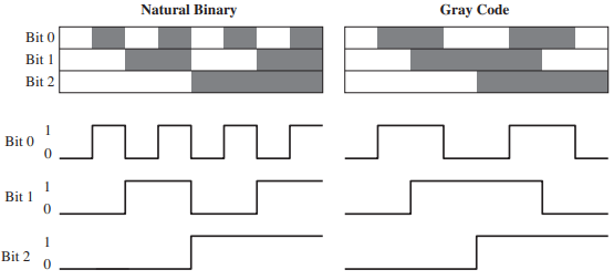
each track of an absolute encoder.
Figure 6 shows the disk pattern (shown as linear for ease of display) and the corresponding output of the encoder for a 3-bit natural binary and gray code absolute encoders. Following Table gives the binary output patterns for both types of encoders for the eight different positions of the encoder disk.
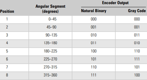
and gray code.
Notice that this 3-bit absolute encoder (which has three tracks) can measure eight distinct absolute positions, each 45 degree in size (i.e., 0–45, 45–90, . . . etc). Commercial absolute encoders have typically 10-bit (or 10 tracks) or higher resolution, which give them an angular resolution of 360/1024 degrees or less.
With the use of a geared motor, the resolution of the angular measurement of the output shaft increases by the gear ratio factor. To use an absolute encoder for multi-revolution measurement, multiple disks need to be used. A high-resolution disk is used for the detailed position information and one or more disks are used for counting turns.
For example, to use an absolute encoder having a measurement range of 16 revolutions, two disks are used. The second disk will have four tracks (to indicate 16 different turns) and should be coupled to the high-resolution disk through a 16:1 gear ratio.
If the primary disk has a 10-bit resolution, then this two-disk encoder will measure or 16384 discrete positions. Commercial absolute encoders are available with different types of output. These include parallel digital output, which uses a single line for each bit.
For a multi-turn encoder with a 14-bit disk, this results in an interface cable that has over 30 wires, which increases the cost of the encoder. A smaller sized cable (and hence lower cost) is obtained if an encoder with SPI output is used. The SPI interface uses only three wires for transmitting the data. Other output formats include DeviceNet™, Profibus, and Interbus.
Thanks for reading about “encoder working principle.”