The most common schemes employed for the protection of a three-phase generator stator windings from earth faults phase-to-phase faults make use of circulating current principle.
In these protection schemes, currents at the two ends of the protected section are compared. Under normal conditions, these currents are equal became different on the occurrence of a fault in the protected section. Due to this difference of the currents in the faulty condition, the operating voltage appears across the relay operating coil.
Then the relay closes its contacts, trips the circuit breaker and thus isolates the protected section. Such protective schemes are very effective for earth faults and faults between phases. These protection schemes are as follows:
- Differential Protection of Generator
- Modified differential protection of generators
- Balanced earth fault protection
Now I shall describe these schemes one by one.
Differential Protection of Generator
The schematic arrangement of this protection scheme for three-phase generator is shown in Figure.
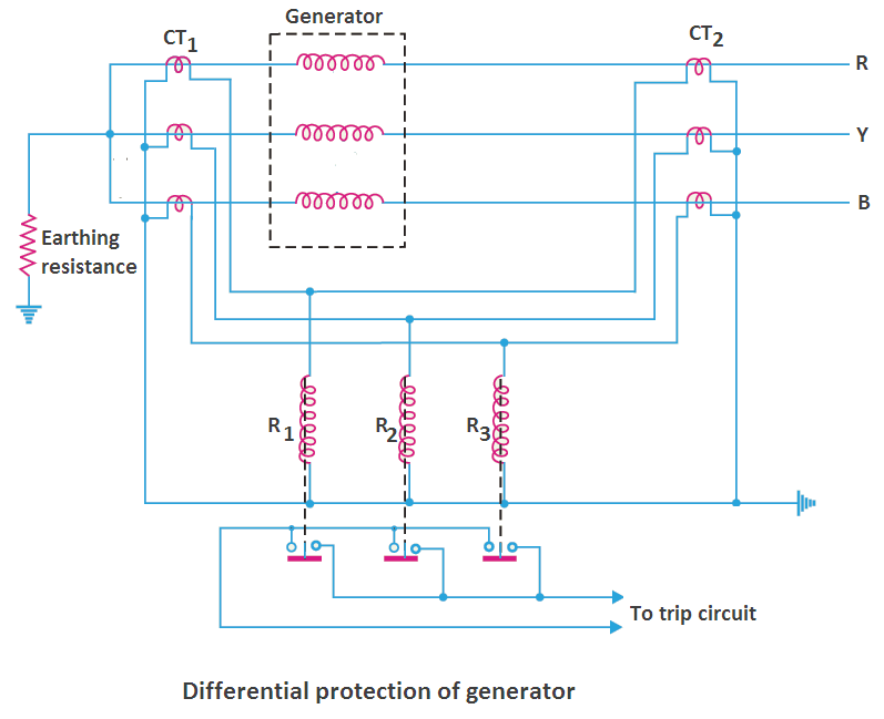
There are two sets of identical CTs, each set is mounted on both sides of the stator phase windings. The secondaries of these CT sets are connected in star at one end and their other ends are connected through pilot wires. The relay coils are connected to the CTs and pilot wires as shown in Figure.
To provide equal burden on the all three CTs, these are connected across equipotential points of the pilot wires. It is obvious, the equipotential points of the pilot wires would be located at the centers of these wires and so the relays are placed midway of the pilot wires.
However, it is always convenient to place the relays adjacent to the CTs near the main circuit breaker. This can be achieved by inserting balancing resistances in series with the pilot wires to shift equipotential points near to the main circuit breaker. Usually the adjustable resistances are used for adjusting the exact balance.

Generally, the electromagnetic type relays arranged for instantaneous operation are used in this protection scheme to clear the fault as quickly as possible.
Under normal operating conditions, the current at the both ends of each winding will be equal, the induced EMFs in the secondaries of CTs will be equal and therefore no current will be flow through the operating coils of the relays. When a phase-to-phase fault or an earth fault occurs in the winding, this condition no longer holds good and the current flows through the operating coil and trips the circuit breaker.
Now suppose, there is an earth fault on the R phase. The current in this phase winding will flow through the core and frame of the generator to earth. The circuit is being completed through the neutral earthing resistance. This will make the current flowing through the primaries of the two CTs in the R phase unequal. And the unequal EMFs will be induced across secondaries of these two CTs, a resultant EMF will appear across the corresponding relay coil. It will trip the circuit breaker.
Limitations of Differential Protection of Generator
To limit the earth fault current, the neutral point of a generator is connected to the earth via a resistor, reactor or transformer. Earthing by means of reactors is very rare and earthing by a transformer is used only in large machines. In such a case, it is not possible to protect the stator winding from earth faults completely by the above-mentioned methods.
When an earth fault take place near the neutral point, very small EMF appears across relay operating coil and very small relay current flows. Also, this current is further decreased by the neutral resistance. Thus, relay may not response to such faults. Actually, by the application of differential protection scheme, we can protect the only 80 to 85% of the stator winding. The remaining 20 to 15% stator winding is unprotected.
Modified Differential Protection of Generators
To overcome the limitations of differential protection scheme, ‘”modified differential protection of generators” scheme has been developed. The schematic diagram of this system is shown in Figure.
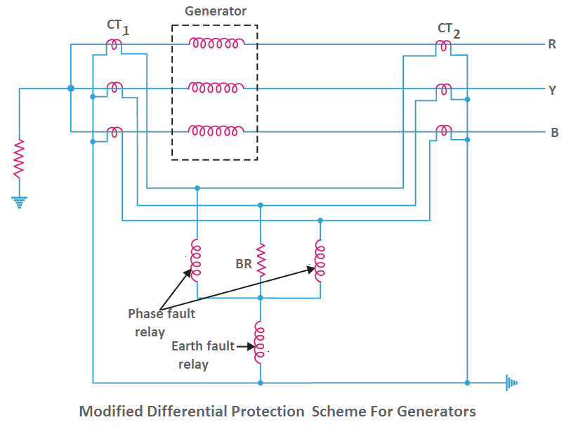
In this scheme, two relays are used for phase fault protection and the third relay is used for only earth fault protection.
On the occurrence of a phase-to-phase fault, the operating current only flows through phase fault relay and earth fault relay remains intact in this situation. The operating current flows through earth fault relay at the time of earth fault only. Therefore, we can set the earth fault relay to a very low value and can protect a greater percentage of the stator winding.
Balanced Earth-Fault Protection
In small-size generators, the neutral ends of the stator windings are often connected internally to a single terminal. Therefore, it is not possible to use “differential protection of generators” or “modified differential protection of generators” schemes described above because the neutral connection of each phase winding is not accessible.
Under these circumstances, balanced earth-fault protection scheme is applied. This scheme provides only protection against earth faults. The phase-to-phase faults cannot be sensed by this scheme until they develop into earth-faults.
The schematic arrangement of a balanced earth-fault protection for 3-phase generator is shown in Figure. It consists of three line CTs, one on each phase, one neutral CT and one relay. And the connections are made according to Figure.
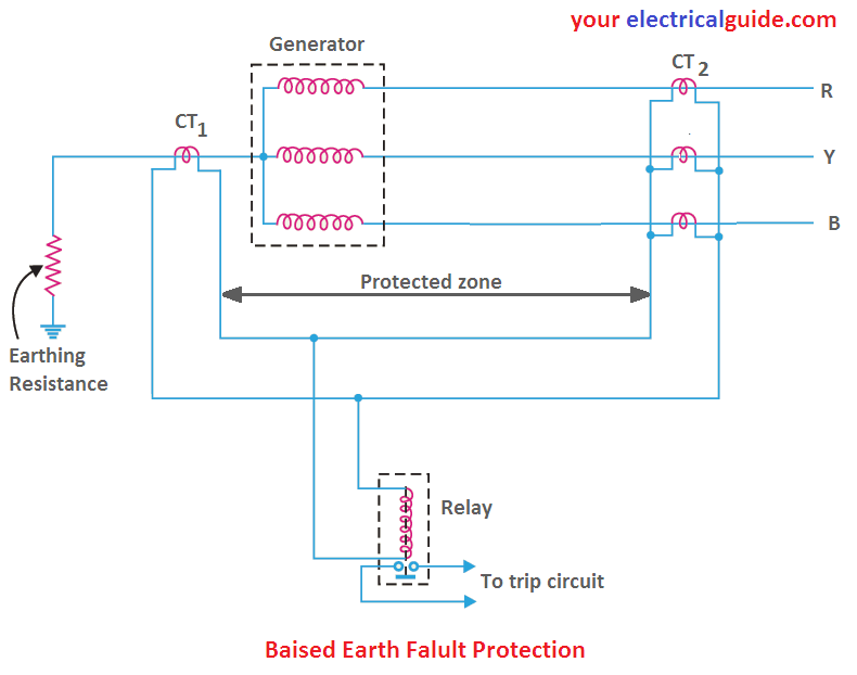
This scheme can protect the generator from the earth fault in the region between the neutral CT and the line CTs. Any earth fault external to this region cannot be sensed by this scheme.
Under normal operating conditions, sum of the induced EMFs in CT2 is equal to the induced EMF in CT1. Therefore, no EMF appears across the relay and it remains de-energized.
But when an earth fault occurs in the protected zone, this balance is get destroyed. And as a result, operating EMF appears across the relay to trip the circuit breaker.
However, in case, when an earth fault develops near the neutral terminal of the generator and neutral is earthed via a resistance, too low EMF appears across and the relay doesn’t operate. It is a main limitation of this scheme.
Thanks for reading about “modified differential protection of generator and alternator”.
Related Posts
- Lightning Arrester Types & Working
- Lightning and Switching Voltage Protection Methods
- Personnel Protective Devices
- How Lightning Arrester Works
- Overvoltage Protection by Lightning Arresters
- Insulation coordination of Electrical Equipment
- MCCB Circuit Breakers
- Differential Protection of Generator & Alternator
- Types of Current Limiting Reactor
- Classification | Types of Protective Relays
- Fuse Selection Criteria
- Protection of Transmission lines by Ground Wires
good