The main tests that are conducted on instrument transformers are as follows:
Polarity Test of Instrument Transformers
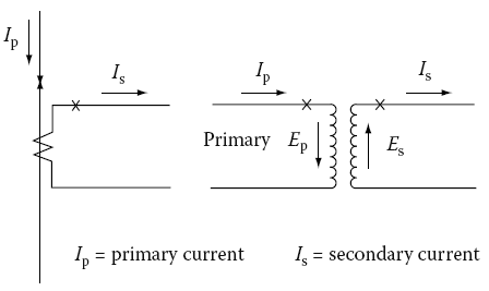
Instrument transformers are marked to indicate the instantaneous direction of primary and secondary currents. Usually, one primary and one secondary terminal are marked with a cross (×) or a dot (•) or a square (■) to indicate the polarity. The following conventions apply to either current or VTs with subtractive or additive polarity.
- The current flowing out at the polarity marked terminal on the secondary side is nearly in phase with the current flowing in at the polarity marked terminal on the primary. This is shown in Figure given below.
- The voltage drop from the polarity to the nonpolarity marked terminals on the primary side is nearly in phase with the voltage drop from the polarity to the nonpolarity marked terminals on the secondary side.
The polarity of instrument transformers can be determined by direct current (DC) or alternating current (AC) tests.
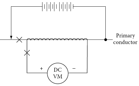
DC test: Connect a DC permanent magnet ammeter of 5 A capacity or less (depending on the transformer ratio) across the CT secondary terminal. The marked secondary terminal of the transformer should be connected to the plus (+) ammeter terminal. Then connect a 7.5 V battery to the primary side such that the negative terminal is connected to the unmarked primary terminal of the transformer.
Make an instantaneous contact with the positive battery terminal to the marked terminal of the transformer. A kick or deflection will be noticed on the ammeter. If the kick is in the positive direction (i.e., upscale) upon making the contact, the transformer leads are correctly marked.
If the initial kick is in the negative direction (i.e., downscale), the polarity markings are not correct. See the following Figure for connections of this test.
VTs can be tested by using a DC permanent magnet moving-coil-type voltmeter having a 150 V scale. The test is performed like the test for CTs, except that the voltmeter is connected across the high-voltage terminals of the transformer first, and then the battery voltage is applied to the low-voltage terminals.
AC tests: The following AC methods are used for determining polarity.
Excitation test: This test consists of exciting the transformer high-voltage winding with low voltage and comparing the voltage across the winding with the voltage across both windings in series.
This method is not very practical with transformers with high ratios such as 100:1, because the difference between the two voltages is very small, which cannot be measured with ordinary instruments.
Moreover, there is always a danger of exciting the low-voltage winding instead of the high-voltage winding, thereby producing dangerous voltages on the transformer.
Substitution method: This method involves using a transformer with known polarity. Make connections as for the known polarity transformer, as shown in Figures a and b given below, and then connect the transformer whose polarity is to be determined.
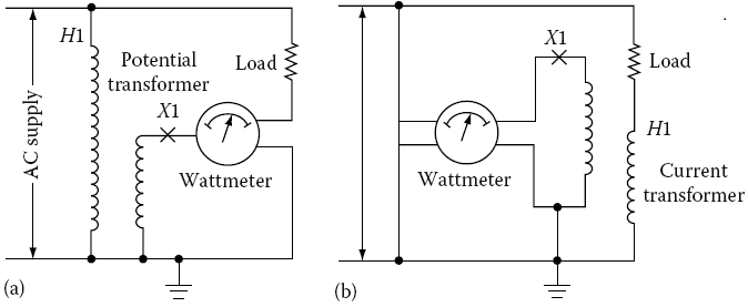
If the ammeter needle deflects in the same direction in both cases, the polarities of the two transformers are the same. By knowing the polarity of the first transformer, the polarity of the second transformer is then determined.
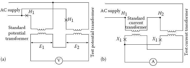
Differential method: The differential method involves exciting the primaries of both transformers (known and unknown polarities) and making a differential measurement with an ammeter or voltmeter.
When the secondaries of two VTs are connected in series, the readings should be the sum of the voltages of two transformers.
Similarly, when the two current secondaries of the transformers are connected in parallel, the ammeter should read the sum of the currents in two transformers. The connections are shown in Figures a and b given below.
Testing for Ratio of Instrument Transformers
The ratio of instrument transformers can be determined by two generally accepted tests.
Voltage method test: A suitable AC voltage, below saturation i.e., below the knee point of the CT saturation curve, is connected to the full secondary winding and a high impedance (20,000 Ω/V or greater) low-range voltmeter is connected in the primary of the CT.
The primary voltage is read on the low-range voltmeter as the secondary voltage is applied to the CT. The turn ratio is approximately equal to the voltage ratio.
In most low and medium-ratio bushing CTs, the saturation level is achieved at about 1 V per turn. The saturation level may be lower than 0.5 V per turn in high-ratio generator CTs and window-type CTs used in metal-clad switchgear.
For very high-ratio CTs, an application of test voltage even lower than 0.5 V per turn may be required to avoid personnel hazards and possible damage to equipment.
Current method test: This method requires a source of high current and an additional CT of known ratio with its own ammeter and a second ammeter for the CT under test.
The test is conducted by injecting the high current test source to a series of values over the desired range and recording the two secondary current readings. The ratio of the CT under test is equal to the turns ratio of the reference CT multiplied by the ratio of the reference CT secondary current to the test transformer secondary current.
When conducting this test avoid using multiple turns of the test conductor through the center of the window-type CT to reduce its ratio because it may produce an abnormal secondary leakage reactance and misleading results in the ratio measurement.
The effect is unpredictable and although small with distributed winding CTs with low secondary burden, it may produce a large error in older CTs particularly when high burdens are connected.
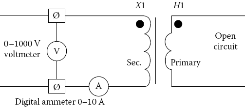
Excitation test: Excitation voltage and current tests can be made on both C (distributed winding) and T class (nondistributed winding) CTs to assess if the CT is performing correctly and to determine if deviations are present.
To perform this test, an AC voltage is applied to the secondary winding with the primary winding open-circuited as is shown in Figure given below. The voltage applied to the secondary winding is varied, and the current drawn by the winding at each selected voltage value is recorded.
A curve is plotted of the secondary voltage versus current for comparison with the original manufacturer’s excitation (saturation) curve. The readings near the knee of the excitation curve are important when plotting this curve.
For multitap ratio CTs, the highest tap should be used provided that the current transformer can be saturated at the selected tap with the test equipment available.
The ammeter used for this test should be a root-mean-square (RMS) instrument and the voltmeter should be an average reading voltmeter calibrated to give the same numerical indication as an RMS voltmeter.
Deviations from expected results or in comparison to the manufacturer data may indicate a turn-to-turn short, distorted waveform of test voltage or the presence of a conducting path around the CT core.
Caution should be taken to minimize energizing the CT at voltages above the knee of the excitation curve any longer than is necessary to take the readings.
This test can also be conducted by energizing the CT primary winding from a high-current test source and plotting the data as primary exciting current versus secondary open-circuited voltage.
The current must be divided by the CT ratio for comparison with the manufacturer’s excitation curve data.
Winding and Lead Resistance Measurements
The internal resistance of CT windings and external impedance (including lead resistance) is required for relay setting calculations, and for calculating ratio correction error when applying CTs.
The internal winding resistance and the lead resistance can be calculated or measured with a resistance bridge. If it is desired to separate the winding resistance and lead resistance, the resistance of a full winding and of a tap then should be measured.
All measurements should be made at the CT short-circuiting terminal block. After completion of this test, the CT should be demagnetized to remove any residual magnetism.
Burden Measurements
For relay applications and for calculating CT ratio correction factors, burden measurements may be necessary. In such cases, the total burden of the circuit, which is the sum of the internal CT burden and the externally connected burden must be determined.
The internal burden is the resistance of secondary winding and the lead resistance from the winding to the short-circuiting terminal block.
The internal burden can be converted to volt-amperes at rated secondary current. The external burden can be measured in volt-amperes by measuring the voltage required to drive the rated current through the connected burden (load).
CT Remanence
The residual magnetism of a CT is known as remanence. The performance of both class C and T CTs is influenced by remanence.
The core of the CT is subject to hysteresis, i.e., when current is interrupted the flux density in the core does not become zero when the current does. When flux in the core is high due to high current or because the current contains a high DC component and when this current is interrupted, the residual magnetism in the core will be high, possibly being above the flux equivalent of the knee point on the excitation curve.
When the CT is next energized, the flux changes will begin from the remanence value and therefore may lead to the saturation of the CT. When this occurs, much of the primary current is used for exciting the core, thereby significantly reducing and distorting the secondary output. This condition can be corrected by demagnetizing the core of the CT.
This can be accomplished by applying a suitable variable alternating voltage to the secondary, with an initial magnitude sufficient to force the flux density above the saturation point, and then decreasing the applied voltage slowly and continuously to zero. Test connections are identical to those shown in the above Figure (Excitation test circuit of a CT) for performing this test.
Thanks for reading about “instrument transformer testing procedure”