Instrument transformers are essential parts of many electrical metering and relaying systems. The quality of instrument transformers will affect directly the overall accuracy and performance of these systems. Instrument transformer performance is critical in protective relaying since the relays can only be as good as the instrument transformers. They serve two basic functions:
- To change the magnitude (but not the nature) of the primary voltage and current to secondary values to 120 V and 5 or 1 A where relays, meters, or other devices can be applied
- To provide isolation between primary and secondary circuits for equipment and safety of personnel
When relays compare the sum or difference of two or more currents or the interaction of voltages and currents, the relative direction of the current must be known. The direction of current flow can be determined by knowing the instrument transformer polarity.
Polarity markings are normally shown on instrument transformers; however, they can be determined in the field if necessary. Several aspects of current and voltage instrument transformers are discussed next.
Current Transformers
Current transformers (CTs) are designed for connection in the primary circuit (either in series or around the primary circuit). The secondary current of the transformer bears a known relationship with the primary current. Any change in the primary current is reflected in the secondary circuit.
Relays, meters, and other devices are connected to the secondary terminals of the CTs.
CTs are made in many different ratios, different voltage insulation systems, and for different environmental conditions such as indoor or outdoor use. Generally, the following types of construction are used for CTs.
Wound type: In this type, more than one primary turn is frequently used to obtain low exciting current and high accuracy. The usual current ratings for this type of transformer are 800 A and below.
Bar-primary type: In this type, the primary consists of a single bar extending through the core, which is connected in series with the circuit conductor. This type of construction is suited to withstand the stresses of heavy over-current. The usual current rating for this type of transformer is 1200 A or above to provide sufficient ampere-turns for good accuracy.
Window type: The window-type CT contains no primary winding. The CT has an insulated hole through the core and secondary windings. The circuit conductor is inserted through the window of the CT, and thus this conductor then becomes the primary of the CT.
Bushing type: The bushing-type CT is similar to the window-type. It has a circular core that is designed to fit on the bushing of a power transformer, circuit breaker, or other apparatus. The secondary windings are wound on the circular core and can be tapped to give multiple ratios. This transformer is mostly used for relaying purposes where high accuracy at normal current value is not extremely important.
Double-secondary type: A double-secondary transformer is actually two transformers, each transformer having its own core. This type of transformer occupies less space than two single-secondary winding transformers. The double-secondary winding transformer permits instruments, relays, or other devices to be separated if required.
Split-core type: This is a window-type CT with hinged cores, which permit them to be installed on buses or other circuits.
Air-core type: The air-core CT is used where saturation of the iron core due to high fault currents is a problem. The air-core transformer has relative constant error over a wide range of overcurrent and transient conditions.
Tripping transformers: Several types of small and inexpensive transformers are available for protective control functions. These transformers are not made with the same accuracy as instrument transformers.
Auxiliary transformers: Auxiliary transformers are used to adjust the difference in ratio between different CTs. These transformers are connected in the secondary circuits of main CTs.
CT Accuracy Standards
CTs can be divided into two categories for purposes of establishing accuracy standards:
- accuracy standard for metering CTs, and
- accuracy standard for relaying CTs.
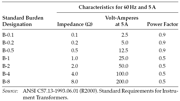
Since accuracy is a function of the burden on the CT, standard burdens have been established.
Accuracy has been established at various burden values. The standard burdens established by American National Standard Institute (ANSI) C57.13-1993(R2003) are shown in folowing Table. The performance rating is based on 5 A secondary current unless otherwise specified.
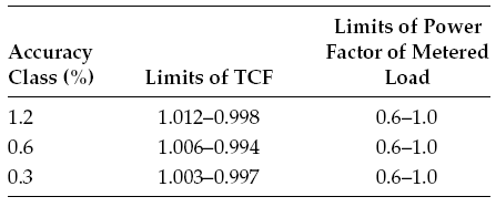
Accuracy Classes for Metering: The ANSI accuracy classes for the metering state that the transformer correction factor (TCF) should be within specified limits when the power factor of the metered load is from 0.6 to 1.0 lagging for a specified standard burden, at 100% of the rated primary current. CTs for metering service have accuracy classes of 0.3%, 0.6%, and 1.2%.
Accuracy Classes for Relaying: A relaying accuracy under the ANSI 57.13-1968 standard is designated by symbols C and T.
- C-type CTs have a single primary turn and distributed secondary windings. For C-type CTs, the ratio error can be calculated. The majority of these CTs are bushing type and are rated at 600 V since they do not have any physical connection with the primary circuit.
- T-type CTs are constructed with more than one primary turn and undistributed windings. The primary windings are insulated and braced for the primary voltage. Because of the physical space required and the fringing effects of nonuniformly distributed winding, because there is a flux that does not link both the primary and secondary windings. The leakage flux has a significant effect on the CT performance and it is not possible to calculate the ratio correction error using the burden and excitation characteristics. Therefore, the ratio correction must be determined by testing for the T-type CTs.
- The secondary terminal voltage rating for the C-type and T-type CTs is the voltage that the transformer will deliver to a standard burden (as listed in Table given below) at 20 times normal secondary current.
- The transformer ratio error must be limited to 10% for all currents from 1 to 20 times normal current for burdens not to exceed those listed in Table given below.
K-type: The K classification was established in the 1993 revision of the C57.13 standard. The K-type CTs are designed to have knee-point voltage of at least 70% of the secondary terminal voltage rating. The K-type is similar to C-type CTs, i.e., their design is based on the principle that the leakage flux in the core does not have an appreciable effect on the ratio of the CT within the limits of current and burden.
To specify a CT under the new standards, one needs only to select either a class C or T transformer and then specify the burden. The first term of the burden classification of a CT identifies the construction type of CTs and the second term describes the voltage rating that can be delivered by the full winding at 20 times rated secondary current without exceeding 10% ratio correction (error).
The ANSI voltage rating applies to the full winding, and if less than full winding is used, the voltage rating is then reduced in proportion to the turns used.
As an example, a CT C200 or T200 means that a ratio correction error will not exceed 10% for values from 1 to 20 times rated secondary current (5 A) with a standard 2.0 Ω burden.
- The C classification covers bushing transformers, and the T classification covers any other transformer
- The secondary voltage values are 10, 20, 50, 100, 200, 400, and 800 V based on 1 to 20 times the normal current standard burdens listed in above Table (Standard Burdens for CTs).
Voltage (Potential) Transformers
VTs are designed for connecting line-to-line or line-to-neutral. The purpose of the VT is to provide an isolated secondary voltage that is an exact proportionate representation of primary voltage. However, transformers draw core-magnetizing current from the primary circuit, and a constant error results independent of the burden connected to it.
Also, variable error results due to load or burden current flowing through the effective impedance of the transformer. The total error is the sum of these two errors under any burden condition.
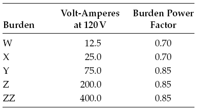
The ANSI standard C57.13-1993(R2003) lists the classification of VTs encountered in service as W, X, Y, Z, and ZZ. The standard burden designations are shown in Table given below for these VTs.
Accuracy classes are based on the requirement that the TCF be within specified limits when the power factor of the metered load is between 0.6 and 1.0 lagging for a specified burden and at voltages from 90% to 110% of rated transformer voltage. The ANSI accuracy classes for VTs are shown in Table given below.
The ratings of VTs encompass the following:
- Insulation class and basic impulse level.
- Rated primary voltage and ratio.
- Accuracy ratings at standard burdens.
- Thermal burden, that is, the maximum burden the transformer can carry at rated secondary voltage without exceeding its temperature rise, above 30°C ambient.