21. Two things which are same for primary and secondary of transformer are
(i) ampere-turns and voltage per turn
(ii) resistances and leakage reactances
(iii) currents and induced voltages
(iv) none of the above
Answer: (i) ampere-turns and voltage per turn
22. A transformer operates poorly at very low frequencies because
(i) permeability of core is increased
(ii) magnetising current is abnormally high
(iii) primary reactance is too much increased
(iv) none of the above
Answer: (ii) magnetising current is abnormally high
23. If a power transformer is operated at very high frequencies then
(i) primary reactance is too much increased
(ii) primary will draw large power
(iii) core losses will be excessive
(iv) none of the above
Answer: (iii) core losses will be excessive
24. The primary leakage flax links
(i) primary winding only
(ii) secondary winding only
(iii) both primary and secondary windings
(iv) none of the above
Answer: (i) primary winding only
25. The effect of leakage flux in a transformer is to ……. ……..
(i) increase copper losses
(ii) decrease copper losses
(iii) cause voltage drop in the windings
(iv) none of the above
Answer: (iii) cause voltage drop in the windings
26. Leakage flux iu a transformer occurs because
(i) iron core has high permeability
(ii) air is not a good magnetic insulator
(iii) applied voltage is sinusoidal
(iv) transformer is not an efficient device
Answer: (ii) air is not a good magnetic insulator
27. The mutual flux in a transformer remains constant at all loads because
(i) applied voltage and frequency are constant
(ii) leakage flux is small
(iii) iron core is used
(iv) losses are small
Answer: (i) applied voltage and frequency are constant
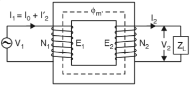
28. Fig. 2 shows an actual transformer on load. The currents I’2 and I2 will be
(i) in phase
(ii) 180° out of phase
(iii) 90° out of phase
(iv) none of the above
Answer: (ii) 180° out of phase
29. The relation between primary ampere-turns and secondary ampere-turns in Fig. 2 is
(i) N1I’2 = N2I2
(ii) N1I1 = N2I2
(iii) N1Io = N2I2
(iv) none of the above
Answer: (i) N1I’2 = N2I2
30. The relation between I‘2 and I2 in Fig. 2 is
(i) I’2 = (N1/N2)I2
(ii) I’2 = (N2/N1)I2
(iii) I’2 = (N2/N1)2I2
(iv) I’2 = (N1/N2)2I2
Answer: (ii) I’2 = (N2/N1)I2
31. If N2/N1 = 0.1 in Fig. 2 and I2 = 500 A, then I1, is nearly equal to
(i) 5000 A
(ii) 50 A
(iii) 5 A
(iv) none of the above
Answer: (ii) 50 A
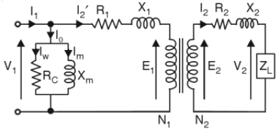
32. Referring to the approximate equivalent circuit of an actual transformer on load in Fig. 3, the secondary resistance R2 when transferred to primary becomes
(i) (N1/N2)2R2
(ii) (N2/N1)2R2
(iii) (N1/N2)R2
(iv) (N2/N1)R2
Answer: (i) (N1/N2)2R2
33. Referring to Fig. 3, the secondary leakage reactance X2 when transferred to primary becomes
(i) (N1/N2)X2
(ii) (N2/N1)X2
(iii) (N2/N1)2X2
(iv) (N1/N2)2X2
Answer: (iv) (N1/N2)2X2
34. Referring to Fig 3, we have . .
(i) I1N1 = I2N2
(ii) I2’N1 = I2N2
(iii) I1N2 = I2N1
(iv) none of the above
Answer: (ii) I2’N1 = I2N2
35. Referring to Fig 3, the secondary load voltage V2 when transferred to primary becomes
(i) (N1/N2)2V2
(ii) (N2/N1)2V2
(iii) (N1/N2)V2
(iv) (N2/N1)V2
Answer: (iii) (N1/N2)V2
36. Referring to Fig. 3, if V1 = 100 V, Iw = 3 A and Im = 4 A, then, Io will be
(i) 7 A
(ii) 1 A
(iii) 5 A
(iv) none of the above
Answer: (iii) 5 A
37. For the values given in the above question, the iron loss in the transformer will be
(i) 300 W
(ii) 500 W
(iii) 400 W
(iv) none of the above
Answer: (i) 300 W
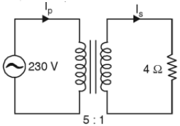
38. In Fig. 4, the primary will see an impedance of
(i) 20 Ω
(ii) 100 Ω
(iii) 1.25 Ω
(iv) none of the above
Answer: (ii) 100 Ω
39. The primary current Ip in Fig. 4 will be
(i) 46 A
(ii) 23 A
(iii) 2.3 A
(iv) none of the above
Answer: (iii) 2.3 A
40. The secondary current Is in Fig. 4 will be
(i) 11.5A
(ii) 46A
(iii) 23 A
(iv) none of the above
Answer: (i) 11.5A