Functional Model of Thermoelectric Circuits
The commonplace obscure problems of thermoelectric circuits are difficult to visualize without a graphic tool. Conventional electrical circuit diagrams conceal the actual thermoelectric emf sources, unrecognized thermoelements, incorrect pairings, incidental junctions, and changing functions that often cause significant hidden thermometry error. The spurious “junction-source” model conceals the fact that all thermoelectric problems occur apart from the measuring junction.
A general-purpose model of thermoelectric circuits shows what junction temperature structures and relationships must be maintained for reliable thermoelectric thermometry and why. This nontraditional Functional Model of Thermoelectric Circuits, combines
- a basic thermoelectric circuit element,
- a single fundamental law that describes the sensitivity of that element,
- a set of practical corollariesfrom the law thatreveal practical implications, and
- an informal T/X graphic tool for circuit visualization and to aid analysis.
Basic Thermoelectric Circuit Element
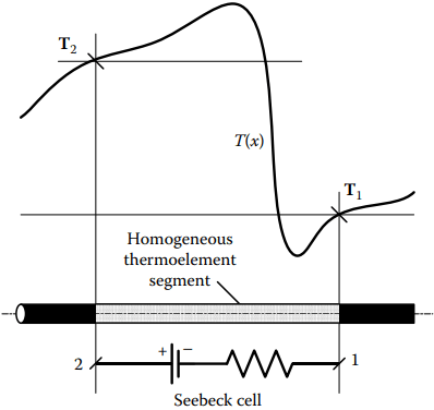
A Seebeck emf cell (Figure 1) is any thermoelectrically homogeneous nonisothermal segment of material M of any length within any thermoelement. (An overall inhomogeneous thermoelement is composed of such locally homogeneous segments.) Seebeck emf is dependent on cross section for different metals only if dimensions are less than 50 – 3500 Å.
Each such homogeneous segment across which a net temperature difference, ∆T, exists is a non ideal voltage source with resistance R(T). (Thermocouple thermometry is rarely of very fast transient temperature change so circuit capacitance and inductance usually are irrelevant.)
Therefore, for accurate thermometry, the Seebeck source emf must be observed in an “open-circuit” mode (i.e., current effectively nulled by high input resistance.) Any IR voltage drop due to current through the resistive thermoelements allowed by too-low input resistance of the voltage monitor lowers the net voltage from the source emf and causes significant error unless compensated.
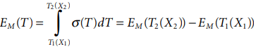
The emf from each Seebeck Cell is
∆EM(T) = EM(T2) − EM(T1).
Simply, the net Seebeck emf of the cell can be determined as the difference between the tabulated emf value for the point at T2 and that value for the point at T1, both referenced to Tr. Any segments of materials A and B that happen momentarily to share a pair of endpoint temperatures are thermally paired, regardless of their location, proximity, or connectivity in a circuit.
The net relative emf for such a pair is ∆EAB(T) = EAB(T2) − EAB(T1).
For calculation alone, they need not even be electrically joined. Either relative properties of thermally paired thermoelement segments or absolute properties of individuals can be used in analysis. Seebeck properties of a pair, each relative to a third shared reference material, such as standardized Pt-67, also can be used.
Either the Seebeck coefficient, or the sense of the temperature increment across a segment, or both of them, can be either positive or negative. Therefore, unlike an electrochemical cell, the polarity of a Seebeck cell within a circuit depends momentarily both on the material and on the sense of temperature difference across the segment. Cell polarity—and even its function—change with temperature distribution.
Law of Seebeck emf
Equation dE = σ(T)dT, is invoked by all quantitative descriptions of the Seebeck effect, whether the description attributes emf to thermoelements or wrongly to junctions. All, in effect, agree that it is the only functional law that governs the Seebeck emf. In this Functional Model, it is named the sole Law of Seebeck emf.
The Functional Model recognizes that every thermoelectric aspect of circuit behavior follows from this one simple relation. Note: If this simple relationship does not apply, then accurate thermometry is not possible.
Corollaries from the Seebeck Law
Corollaries express useful and practical truths and implications that may not be obvious from a concisely stated law. Here, they encourage a distinctive way to view real thermoelectric circuits. From the Law of Seebeck emf, five particularly instructive practical corollaries are recognized. The Functional Model corollaries are stated in Table 70.1. These are corollaries of
- functional roles,
- functional determinacy,
- temperature determinacy,
- emf determinacy, and
- Seebeck emf.
They are to be comprehended, not memorized. These corollaries relate more directly to practical thermoelectric thermometry than do the commonplace archaic statements of three thermocouple “laws” that actually also are only corollaries of the sole Seebeck Law, not “laws” themselves. The significance of the five functional corollaries is illustrated by a nonconventional T/X sketch.
Corollaries from the Law of Seebeck emf
In any circuit of electrically conducting dissimilar material segments that have absolute Seebeck coefficients σ(T), that are each thermoelectrically homogeneous, and each of which follow the Seebeck Law,
dE(T) = σ(T)dT
1. The corollary of functional roles: In a thermoelectric circuit, for any temperature distribution, there are three momentary thermoelectric functional roles: Seebeck emf sources, “conductors,” and junctions:
- Real thermoelectric junctions are interfaces that ohmically connect dissimilar materials
- “Conductors” are thermoelement segments that, in effect, individually or in combination, contribute no net Seebeck emf
- All other segments are sources of Seebeck emf
2. The corollary of functional determinacy: Thermoelectric roles of segments cannot be predetermined by physical construction, material choice, or circuit arrangement alone; they are determined by temperature distribution.
3. The corollary of temperature determinacy: In a thermoelectric circuit, only a single junction temperature can be determined from the net emf and only if the individual or relative temperatures of all other real junctions are known.
4. The corollary of emf determinacy: Seebeck emf occurs only in thermoelements, but the circuit net Seebeck emf is determined by the temperatures of only real junctions.
5. The corollary of Seebeck emf: The Seebeck emf of any thermoelement segment of material, M, of any cross-section area, a with endpoint temperatures, T1 and T2, is independent of temperature distribution or of temperature gradients, dT/dx, between those endpoints because it is determined only by
T/X Sketch
To decrease the length of this web-page, content of this section is placed on another page. To access that content, please follow the link.
Related Posts
- Thermocouple Working Principle
- Absolute Seebeck Effect
- Basic Thermocouple Circuits
- Extensions of Thermocouple
- Functional Model of Thermoelectric Circuits
- T/X Sketch of Dual-Reference Junction Circuit
- Applications of Functional Model
- Characteristics of Thermocouples
- Thermocouple Hardware
- Thermocouple Junction Styles
- Active Tests of Thermocouple
- Calibration of Thermocouples
- Thermocouple Thermometry Practice
- Distinctive Thermocouple Noise Problems