T/X Sketch of Dual-Reference Junction Circuit
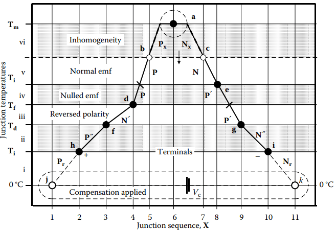
An informal T/X sketch, Figure 1, plots one present distribution of temperatures, T, of all junctions against the sequence, X, in which those junctions occur in the circuit. (X is not a space variable; slopes do not represent temperature gradients.) A T/X sketch is not rendered to scale. It is not for graphic calculation. It is only for visualization of momentary functions and consequences.
The T/X sketch clearly illustrates how thermoelements, not junctions, function as the physical Seebeck sources. This non-traditional T/X sketch is one proper form of thermoelectric schematic that necessarily acknowledges
- electrical connectivity,
- junction relative temperatures,
- leg materials, and
- any applied reference temperature compensation.
The sketch forces attention to problem areas that are not apparent from a conventional electrical schematic nor from alternative traditional E(T), E(x), or T(x) plots. It directs attention to inherently hidden errors so that they can be recognized and avoided.
Note: The practical T/X sketch requires no more information than is essential for successful thermometry. If the relative temperatures of incidental junctions are not known and properly controlled, then thermoelectric thermometry is of indefinite accuracy regardless of any perceived calibration.
Junctions
Filled circles represent real physical junctions between dissimilar thermoelements. Measuring junctions are those of which an unknown temperature is to be determined. Reference junctions are any of which the temperature must be accurately known and controlled for thermometry.
Other real junctions are incidental junctions. For incidental junctions, relative temperatures must be controlled to avoid error. Open circles importantly represent connections only presumed to be splice connections between identical thermoelements. (Consequentially, these joins, unrecognized, might actually be real junctions between merely similar thermoelements or between thermoelements unintentionally misconnected in reversed polarity.)
Open circles can also depict indefinite invisible boundaries between initially homogeneous segments and any local segments made inhomogeneous along thermoelements damaged in use. These might not be visible in the physical circuit though effectively they are real junctions.
Thermoelements
Thermoelements between the junctions may be shown simply as solid straight lines. Optionally, a conventional electrical cell symbol with indicated polarity and a resistor symbol for segments in each temperature zone may be shown on each leg for clarity, as in some electrical schematics.
Usually, these distinctly thermoelectric electrical functions are just understood. Circuit analysis is the same as for regular electrical circuits except that, momentarily, both thermoelectric cell emfs and their polarities are temperature-determined. If numerical estimation of plausible magnitudes of errors is wanted, both the actual and relative temperatures of incidental junctions must be estimated.
Isotherms
Lines are drawn across the sketch at the temperature of every real junction. Isotherms through two adjacent junction temperatures bound a temperature zone that functionally pairs thermoelements. Intercepts of isotherms where they cross thermoelements apart from real junctions may be indicated by tics that identify segment ends that can be viewed as nonfunctional virtual junctions used only for visualization and calculation.
In a strictly series thermoelectric circuit, all thermoelement segments that span a temperature interval between adjacent isotherms occur in pairs. Each zone contributes to the net Seebeck emf.
In such circuits, each temperature zone contributes a specific net relative Seebeck emf. Any temperature zone might include paired segments of several different materials.
For a temperature zone defined by two temperature-adjacent junctions (e.g., d and e in Figure 1), both the sign and the magnitude of the relative emf as well as which materials are paired depend just on whether the temperature of d is greater than or less than that of e.
Reference Temperature Compensation
Complementary nonthermoelectric voltage sources, Vc, are indicated as dashed equivalent virtual thermoelements. Thermocouple monitors or else separate modules might apply such reference junction temperature compensation voltage. It is important to show any compensation voltage source on the T/X sketch.
Some circuits require that compensation not be applied. If applied redundantly or at the wrong junctions, such complementary voltage results in substantial error.
Evaluation of emf
Beyond visualization, optionally, the T/X sketch can support calculation of zone and circuit emfs. When available, the relative Seebeck coefficients of thermally paired materials can be used for direct evaluation of net emf, zone by zone. The values of EAB(T) for each of the thermally paired cells are obtained from the standard thermocouple polynomial defining equations, simpler representations of those equations, tables, or graphs.
Alternatively, the emfs of individualstandardized thermoelements relative to a particular Pt-67 platinum reference, also tabulated in the NIST defining document, can be used. Absolute Seebeck properties for many nonstandardized materials also are known, but are less commonly reported. The relative Seebeck emf from thermoelement segment pairs in all temperature zones is summed from the reference temperature, 0 °C.
Like thermoelements that cross the same temperature zone in opposite temperature directions as the circuit is traversed contribute no net emf (Corollary 1). They cancel. Any such opposed pairs can immediately be eliminated from analysis by inspection as passive “conductors” that, momentarily, are contributing no net emf.
Alternatively, the absolute Seebeck emfs could be summed as the T/X circuit is traversed on the sketch from one instrument terminal (e.g., the negative), to the other terminal. The two approaches can be intermixed.
Related Posts
- Thermocouple Working Principle
- Absolute Seebeck Effect
- Basic Thermocouple Circuits
- Extensions of Thermocouple
- Functional Model of Thermoelectric Circuits
- T/X Sketch of Dual-Reference Junction Circuit
- Applications of Functional Model
- Characteristics of Thermocouples
- Thermocouple Hardware
- Thermocouple Junction Styles
- Active Tests of Thermocouple
- Calibration of Thermocouples
- Thermocouple Thermometry Practice
- Distinctive Thermocouple Noise Problems