Strain Gage Load Cell
The strain-gage load cell consists of a structure that elastically deforms when subjected to a force and a strain-gage network that produces an electric signal proportional to this deformation. Examples of this are beam and ring types of load cells.
Strain Gages
Strain gages use a length of gage wire to produce the desired resistance (which is usually about 120 Ω in the form of a flat coil). This coil is then cemented (bonded) between two thin insulating sheets of paper or plastic. Such a gage cannot be used directly to measure deflection. It has to be first fixed properly to a member to be strained.
After bonding the gage to the member, they are baked at about 195 °F (90 °C) to remove moisture. Coating the unit with wax or resin will provide some mechanical protection. The resistance between the member under test and the gage itself must be at least 50 MΩ. The total area of all conductors must remain small so that the cement can easily transmit the force necessary to deform the wire.
As the member is stressed, the resulting strain deforms the strain gage and the cross-sectional area diminishes. This causes an increase in resistivity of the gage that is easily determined.
In order to measure very small strains, it is necessary to measure small changes of the resistance per unit resistance (∆R/R). The change in the resistance of a bonded strain gage is usually less than 0.5%.
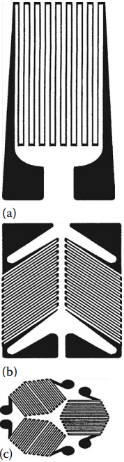
(c) three elements.
A wide variety of gage sizes and grid shapes are available, and typical examples are shown in Figure 1. The use of strain gages to measure force requires careful consideration with respect to rigidity and environment. By virtue of their design, strain gages of shorter length generally possess higher response frequencies (examples: 660 kHz for a gage of 0.2 mm and 20 kHz for a gage of 60 mm in length).
The environmental considerations focus mainly on the temperature of the gage. It is well known that resistance is a function of temperature and, thus, strain gages are susceptible to variations in temperature. Thus, if it is known that the temperature of the gage will vary due to any influence, temperature compensation is required in order to ensure that the force measurement is accurate.
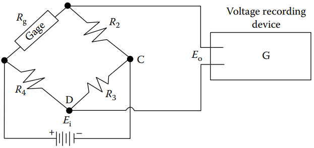
A Wheatstone bridge (Figure 2) is usually used to measure this small order of magnitude. In Figure 2, no current will flow through the galvanometer (G) if the four resistances satisfy a certain condition.
In order to demonstrate how a Wheatstone bridge operates, a voltage scale has been drawn at points C and D of Figure 2.
Assume that R1 is a bonded gage represented by Rg and that initially Equation 1 is satisfied.
If R1 is now stretched so that its resistance increases by one unit (+∆R), the voltage at point D will be increased from zero to plus one unit of voltage (+∆V), and there will be a voltage difference of one unit between C and D that will give rise to a current through C.
If R4 is also a bonded gage and at the same time, R1 changes by +∆R and R4 changes by −∆R, the voltage at D will move to +2∆V.
Also, if at the same time, R2 changes by −∆R and R3 changes by +∆R, then the voltage of point C will move to −2∆V and the voltage difference between C and D will now be 4∆V.
It is then apparent that although a single gage can be used, the sensitivity can be increased fourfold if two gages are used in tension while two others are used in compression.
Similarly, the bridge becomes unbalanced in proportion to the difference in strain when gages are located on the adjacent leg. The strain gage arrangement determines the relationship between the output and the type of strain being measured for axial, shear, bending, and torsional strains.
R1/R4 = R2/R3 …….(1)
The grid configuration of the metal-foil resistance strain gages is formed by a photo-etching process. The shortest gage available is 0.20 mm; the longest is 102 mm.
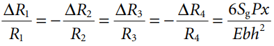
Standard gage resistance is 120 and 350 Ω. A strain gage exhibits a resistance change ∆R/R that is related to the strain in the direction of the grid lines by the expression in Equation 2
∆R/R = Sgε …….(2)
Where, Sg is the gage factor or calibration constant for the gage.
Beam-Type Load Cell
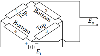
Beam-type load cells are commonly employed for measuring low-level loads. A simple cantilever beam (see Figure 3a) with four strain gages, two on the top surface and two on the bottom surface (all oriented along the axis of the beam), is used as the elastic member (sensor) for the load cell. The gages are wired into a Wheatstone bridge as shown in Figure 3b.
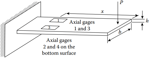
The load P produces a moment M = Px at the gage location (x) that results in the following strains:
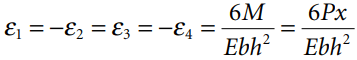
Where,
b is the width of the cross section of the beam,
h is the height of the cross section of the beam.
Thus, the response of the strain gages is obtained from Equation 4:
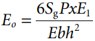
The output voltage Eo from the Wheatstone bridge, resulting from application of the load P, is obtained from Equation 5.
If the four strain gages on the beam are assumed to be identical, then Equation 5 holds:
The range and sensitivity of a beam-type load cell depends on the shape of the cross section of the beam, the location of the point of application of the load, and the fatigue strength of the material from which the beam is fabricated.
Ring-Type Load Cell
Ring-type load cells incorporate a proving ring (see Figure 4) as the elastic element.
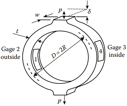
The ring element can be designed to cover a very wide range of loads by varying the diameter D, the thickness t, or the depth w of the ring. Either strain gages or linear variable differential transformer (LVDT) can be used as the sensor.
The load P is linearly proportional to the output voltage Eo. The sensitivity of the ring-type load cell with an LVDT sensor depends on the geometry of the ring (R, t, and w), the material from which the ring is fabricated (E), and the characteristics of the LVDT (S and Ei ). The range of a ring-type load cell is controlled by the strength of the material used in fabricating the ring.