Thermocouple Thermometry Practice
Temperature Ranges
Moderate and High Temperatures: Temperature and duration of exposure are unavoidable environmental variables in thermometry. Other environments can sometimes be controlled.
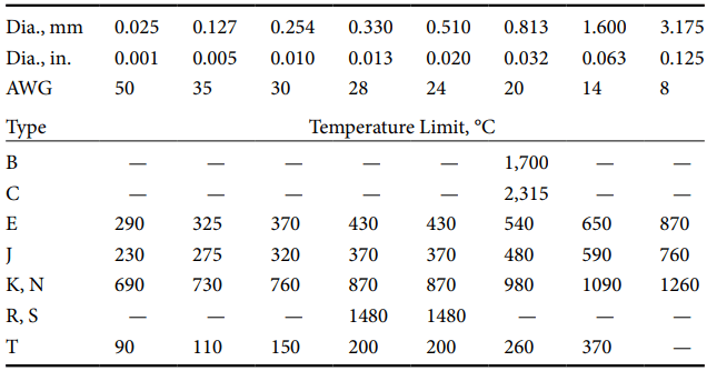
Standard thermocouple tables extend only to the greatest temperature of recommended use for benign protected environments, short durations, and for wire materials of 3 mm or greater diameter. Reduced temperature limits apply for materials of smaller cross section (Table 1).
Degradation of the Seebeck property can occur due to excessive temperature alone, well below the melting point, eventually even well within the range recommended for use. Environmental degradation is accelerated by heat.
Frequent cyclic heating and cooling accelerate damage of MIMS thermocouple. Within the recommended temperature range, damage progresses gradually with time at temperature over periods of weeks to months.
Calibration should be performed quickly, allowing time only for equilibration, and only to the maximum temperature of intended use.
Although thermoelements may not be visibly affected, the Seebeck coefficient of thermoelement segments adjacent to the measuring junction might be substantially degraded.
Very High Temperatures: Type K thermocouples are limited to temperatures up to 1372 °C. Proprietary Platinell® has a Seebeck characteristic similar to Type K with improved stability and recommended upper limit of 1392 °C.
Types R and S extend the range to 1768 °C, and Type B to 1820 °C. Special commercial gold vs. platinum thermocouples of very special design and construction are used for stable precision thermometry to 1000 °C.
Damage by chemical exposure is not reversible, but the precious materials can be recycled. Refractory metal thermocouples are of specially treated materials such as tungsten, rhodium, or rhenium alloys.
Low Temperatures: The scaling functions for use of normal thermocouple material below 0 °C are different than for elevated temperature use of the same thermocouple type. Standardized thermocouple characteristics below 0 °C are based on less data than for higher temperatures.
Also materials manufactured for thermometry at elevated temperatures conform less well to the standard characteristics for cryogenic thermometry than do special modified alloys of the same thermocouple letter type especially made for such use. This quality issue should be discussed with the thermocouple supplier.
Cryogenic Temperatures: Cryogenic thermometry has been loosely defined as measurement of temperatures below 280 K (7 °C). That range broadly overlaps the measure of atmospheric temperatures below the ice point (down to −50 °C) that, along with higher ambient temperatures, often are measured by a single thermocouple system.
A more restrictive definition limits cryogenic thermometry to temperatures below 90 K (−183 °C) (the boiling point temperature of liquid oxygen at 1 atm). The latter definition characterizes as cryogenic only the extremely low-temperature regime over which thermometry involves distinctive severe problems and very different techniques.
The Seebeck properties are degraded at extremely low as well as high temperatures. Common thermoelement materials progressively decrease in thermoelectric sensitivity below the ice point. The Seebeck coefficient of all conductors is insignificant at 0 K (−273.15 °C).
Superconductive materials experience an abrupt drop in Seebeck coefficient to near zero at a characteristic superconducting transition threshold. That threshold is below 10 K for most unalloyed metal superconductors.
Special alloys have been developed to raise the atmospheric pressure superconducting threshold to as much as 138 K—well above the strict cryogenic range. Only between 0 K and a superconductive threshold is it possible directly to observe the absolute Seebeck characteristic of a normal thermoelement by pairing it with a superconductive thermoelement.
Standard Seebeck characteristics are defined for Types E, J, K, N, and T down to −270 °C. The characteristics for Types R and S extend down only to −50 °C. Type B is not characterized below 0 °C. It is not recommended for thermometry below 400 °C because its sensitivity is very small at lower temperatures.
Often, simple passive-type extensions are used for Type B thermocouples near ambient temperature where the thermocouple emf is very small. For very low temperatures, the letter-designated thermocouple material, Type E, is preferred for use down to −233 °C (40 K) because of its higher relative Seebeck coefficient in that range. The less-sensitive Type K and Type T materials are also used in this range.
Below 40 K, special non-standardized alloy combinations, such as Type KP vs. Au/0.07 Fe, are preferred. Some thermoelement alloys experience grain growth and incur serious inhomogeneity under prolonged exposure to deep cryogenic temperatures.
More sensitively at cryogenic temperatures than at elevated temperatures, the Seebeck coefficient of most thermocouple alloys is very strongly dependent on magnetic field. Strong magnetic fields are often involved in cryogenic experiments, so thermo-magneto-electric effects become significant in studies of superconductivity.
Peltier heating at junctions and Thomson heating along thermoelements are current-dependent thermoelectric effects that rarely affect thermometry.
Fortunately, neither effect is significant if thermometry is conducted properly by “open-circuit” measurement. There is no significant thermocouple self-heating as with resistance thermometers.
Thermometry Process
Coupling: As any thermal sensor, the temperature of the measuring junction of a thermocouple must approach and track the temperature of the subject.
Close thermal coupling of the measuring junction to the point of measurement is enhanced by a very thin layer of thermally conducting coupling grease or adhesive, avoiding even thin air gaps. Electrically conducting coupling between junction and subject may be appropriate for noise control.
Thermal coupling and loading problems are aggravated in the measurement of subjects of low thermal mass. Heat transfer is more delayed for surface, liquid, and gas measurements than for internal solid measurements. Centering the measurement point in an isothermal region is preferred.
Even for steady-state measurement, temperature gradients can cause the measuring junction to be at a significantly different temperature from the intended point of measurement.
Transient Thermometry: The very small dimensions possible for the junction and low thermal mass of its adjoining thermoelements well adapt thermocouples to transient thermometry. The Seebeck effect occurs at electronic speed, independent of thermoelement size.
Seebeck emf immediately corresponds to the actual temperatures of all junctions in the circuit. An isolated thermocouple alone has no characteristic response.
Thermal response is necessarily a joint property of the thermoelements at the measuring junction, of its subject, and of the monitoring system. Traditionally, thermocouple transient behavior is represented simply as a first-order exponential step rise time with a time-constant reflecting rise time to respond to 63.2% of an instantaneous temperature step.
The actual forms of response for different geometries are similar yet more complex. Rise-times are often stated for beaded-junction thermocouples of different wire sizes plunged into an air or water stream. The response of actual thermocouples depends on many factors such as junction dimension, material, and style of the junction and of adjacent thermoelements, the thermal properties of the test subject, and thermal coupling, as well as circuitry and the recording electronics.
Butt-welded fine wire and foil thermocouples might respond within 3 ms. Small-diameter MIMS thermocouples with exposed or enclosed junctions in air have response times in the range from fractional seconds to several seconds. Surface contact thermocouples have time constants around 2 or 3 s.
Unlike for static thermometry, in fast transient thermometry, the electrical parameters of the thermocouple and associated circuitry and the dynamic response of the recording system might further slow response time.
Distinctive Thermocouple Noise Problems
To decrease the length of this web page, content of this section is placed on another web page. To access that page, please follow the link.
Thermocouple Modes of Failure
Short or Open Circuit: Failure Thermocouple thermometry has failed when its indications are beyond uncertainty limits required for a measurement.
Thermocouples sometimes do fail “open” as junctions separate or thermoelements corrode, yield, or melt. Special “open-circuit” indication is a promoted feature of many modern thermocouple indicators. If failure is for other reasons, such indicators encourage unwarranted confidence.
More often thermocouples fail before the circuit opens. The more common but less apparent circuit failures are by insidious shunting, shorting, or progressing inhomogeneity of thermoelements. These common faults are not detected by the “open-circuit” indication.
Environmental Damage: Corrosive or reactive environments breach protective sheaths and disrupt circuits. Inhomogeneity is introduced locally in thermoelements. Plastic, ceramic, or fiber insulators are vulnerable to contamination.
The compressed granular insulation of MIMS thermocouples, if exposed, rapidly absorbs moisture that can seriously degrade resistive isolation. Electrically conductive fluid or solid shunts can displace the location of measurement without interrupting temperature indication.
Metallurgical Change: Alloy thermoelements can locally change composition by evaporation of constituents when exposed to vacuum. Appropriate MIMS construction and material selection usually extend life and increase temperature limits, but damage can occur even within apparently fully sheathed assemblies.
Alloy constituents evaporated internally from a sheath or from one thermoelement can migrate and coat adjacent thermoelements even through an insulant. Traces of contaminants can penetrate through pinholes and hairline cracks in metal sheaths and can actually diffuse through intact protective sheaths and affect apparently isolated thermoelements.
Minute trace impurities in sheaths or insulants can interact with thermoelements. Alloy components can migrate from one thermoelement to the otherthrough the measuring junction, but the effect is negligible if the junction region is properly maintained isothermal during measurement.
Excessive distributed strain can locally modify the Seebeck coefficient of one or both thermoelements resulting in temporary or persistent inhomogeneity.
However, very narrowly localized plastic strain as might be introduced by very sharp bends has negligible effect on practical thermometry as is evident from the Functional Model.
Related Posts
- Thermocouple Working Principle
- Absolute Seebeck Effect
- Basic Thermocouple Circuits
- Extensions of Thermocouple
- Functional Model of Thermoelectric Circuits
- T/X Sketch of Dual-Reference Junction Circuit
- Applications of Functional Model
- Characteristics of Thermocouples
- Thermocouple Hardware
- Thermocouple Junction Styles
- Active Tests of Thermocouple
- Calibration of Thermocouples
- Thermocouple Thermometry Practice
- Distinctive Thermocouple Noise Problems