Triac Working
The triac is a three-terminal device essentially equivalent to two SCRs joined in reverse parallel (paralleled but with the polarity reversed) and with their gates connected together. The result is a bidirectional electronic switch that can be used to provide load current during both halves of the AC supply voltage.
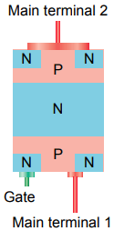
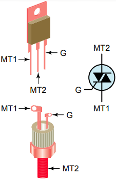
Triac connections, shown in Figure 1, are called main terminal 1 (MT1), main terminal 2 (MT2), and gate (G). The leads are designated this way since the triac acts like two opposing diodes when it is turned on and neither lead always acts like a cathode or an anode.
Gate current is used to control current from MT1 to MT2. From terminal MT1 to MT2 the current must pass through an NPNP series of layers or a PNPN series of layers. The gate is connected to the same end as MT1, which is important to remember when you connect the triac control circuit.
Terminal MT1 is the reference point for measurement of voltage and current at the gate terminal.
The triac may be triggered into conduction by either a positive or a negative voltage applied to its gate electrode. Once triggered, the device continues to conduct until the current through it drops below a certain threshold value, such as at the end of a half-cycle of the alternating current (AC) mains power. This makes the triac very convenient for switching AC loads.
Triac Working
The triac is an almost ideal component for controlling AC power loads with a high (on/off) duty cycle. Using a triac eliminates completely the contact sticking, bounce, and wear associated with conventional electro-mechanical relays.
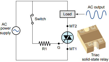
The schematic of a triac switching circuit is shown in Figure 2. Maximum output is obtained by utilizing both half-waves of the AC input voltage. The operation of the circuit can be summarized as follows:
- The circuit provides random (anywhere in half-cycle) fast turn-on of AC loads.
- When the switch is closed, a small control current will trigger the triac to conduct. Resistor R1 is provided to limit gate current to a small control current value.
- When the switch is then opened, the triac turns off when the AC supply voltage and holding current drop to zero, or reverse polarity.
In this way large currents can be controlled even with a small switch, because the switch will have to handle only the small control current needed to turn on the triac.
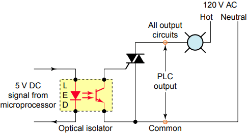
The output module of a programmable logic controller (PLC) serves as the link between the PLC’s microprocessor and field load devices. Figure 3 shows a triac used to switch AC high voltage and current, controlling the on/off state of the lamp.
The optical isolator separates the output signal from the PLC processor circuit from the field load devices. The operation of the circuit can be summarized as follows:
- As part of its normal operation, the processor sets the outputs on or off according to the logic program.
- When the processor calls for the lamp to be on, a small voltage is applied across the LED of the optical isolator.
- The LED emits light, which switches the photo-transistor into conduction.
- This in turn switches the triac into conduction to turn on the lamp.
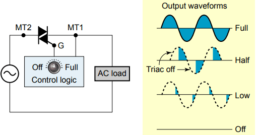
The schematic circuit of Figure 4 illustrates how a triac can be used to control the amount of power applied to an AC load. When used for this type of application, a control logic triggering circuit is needed to ensure that the triac conducts at the proper time. The operation of the circuit can be summarized as follows:
- The trigger circuit controls the point on the AC waveform at which the triac is switched on. It proportionally turns on a percentage of each power line half-cycle.
- The resulting waveform is still alternating current, but the average current value is adjustable.
- Since the trigger can cause it to trigger current in either direction, it is an efficient power controller from essentially zero to full power.
- In universal motor circuits, varying the current will change the speed of the motor.
The diac is a two-terminal device that behaves like two series diodes connected in opposite directions. Current flows through the diac (in either direction) when the voltage across it reaches its rated breakover voltage .
The current pulse produced when the diac changes from a nonconducting to a conducting state is used for SCR and triac gate triggering.
Typically, light dimmers are manufactured with a triac as the power control device. A light dimmer works by essentially chopping parts out of the AC voltage. This allows only parts of the waveform to pass to the lamp.
The brightness of the lamp is determined by the power transferred to it, so the more the waveform is chopped, the more it dims.
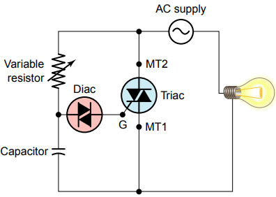
A simplified triac/diac incandescent lamp dimmer circuit is shown in Figure 5. The operation of the circuit can be summarized as follows:
- With the variable resistor at its lowest value (minimum resistance), the capacitor will charge rapidly at the beginning of each half-cycle of the AC voltage.
- When the voltage across the capacitor reaches the breakover voltage of the diac, the capacitor voltage discharges through the gate of the triac.
- Thus, the triac conducts early in each half-cycle and remains on to the end of each half-cycle.
- As a result, current will flow through the lamp for most of each half-cycle and produce maximum lamp brightness.
- If the resistance of the variable resistor is increased, the time required to charge the capacitor to the breakover voltage of the diac increases.
- This causes the triac to fire later in each half-cycle. So, the length of time current flows through the lamp is reduced, and less light is emitted.
- The diac prevents any gate current until the triggering voltage has reached a certain repeatable level in either direction.
The average current and voltage rating for triacs is much smaller than that for SCRs. Also, triacs are designed to operate at much lower switching frequencies than SCRs and have more difficulty switching power to highly inductive loads.
Triacs, like SCRs, usually fail shorted rather than open. Shorted triacs can usually be detected with an ohmmeter check.
Measure the MT1 to MT2 resistance in both directions; a good triac should measure near infinity in both directions.
Like SCRs, triacs can fail in other—possibly peculiar—ways, so substitution or bypassing may be necessary to rule out all possibilities.
Related Posts
- Operation of Thyristors
- Static Characteristics of SCR | Thyristor
- Silicon Controlled Rectifier Function
- Applications & Characteristics of SCR
- SCR Selection Criteria
- Thyristor | SCR Specifications and Ratings
- Operation of Triac & GTO
- Triac Working
- Characteristics, Operation, & Construction of IGBT
- Freewheeling Diode in Controlled Rectifier
- Reverse Recovery Characteristics of Power Diode