Programmable logic controllers are now the most widely used industrial process control technology. A programmable logic controller (PLC) is an industrial grade computer that is capable of being programmed to perform control functions.
The programmable controller has eliminated much of the hardwiring associated with conventional relay control circuits. Other benefits include easy programming and installation, high control speed, network compatibility, troubleshooting and testing convenience, and high reliability.
The programmable logic controller is designed for multiple input and output arrangements, extended temperature ranges, immunity to electrical noise, and resistance to vibration and impact. Programs for the control and operation of manufacturing process equipment and machinery are typically stored in battery-backed or nonvolatile memory.
Introduction to Programmable Logic Controllers
A PLC is an example of a real-time system since the output of the system controlled by the PLC depends on the input conditions. The programmable logic controller is, then, basically a digital computer designed for use in machine control. Unlike a personal computer, it has been designed to operate in the industrial environment and is equipped with special input/output interfaces and a control programming language.
The common abbreviation used in industry for these devices, PC, can be confusing because it is also the abbreviation for “personal computer.” Therefore, most manufacturers refer to their programmable controller as a PLC, which stands for “programmable logic controller.”
Initially the PLC was used to replace relay logic, but its ever-increasing range of functions means that it is found in many and more complex applications. Because the structure of a PLC is based on the same principles as those employed in computer architecture, it is capable not only of performing relay switching tasks but also of performing other applications such as timing, counting, calculating, comparing, and the processing of analog signals.
How a PLC Operates
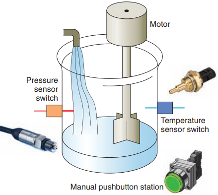
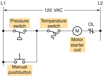
To get an idea of how a PLC operates, consider the simple process control problem illustrated in Figure 1. Here a mixer motor is to be used to automatically stir the liquid in a vat when the temperature and pressure reach preset values. In addition, direct manual operation of the motor is provided by means of a separate pushbutton station. The process is monitored with temperature and pressure sensor switches that close their respective contacts when conditions reach their preset values.
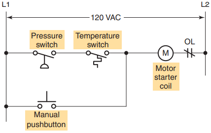
This control problem can be solved using the relay method for motor control shown in the relay ladder diagram of Figure 2 . The motor starter coil (M) is energized when both the pressure and temperature switches are closed or when the manual pushbutton is pressed.
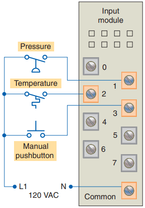
Now let’s look at how a programmable logic controller might be used for this application. The same input field devices (pressure switch, temperature switch, and pushbutton) are used. These devices would be hardwired to an appropriate input module according to the manufacturer’s addressing location scheme.
modular configured input module.
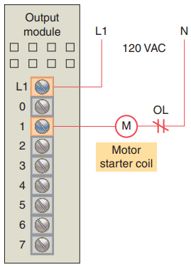
Typical wiring connections for a 120 VAC modular configured input module is shown in Figure 3. The same output field device (motor starter coil) would also be used. This device would be hardwired to an appropriate output module according to the manufacturer’s addressing location scheme. Typical wiring connections for a 120 VAC modular configured output module is shown in Figure 4.
Next, the PLC ladder logic program would be constructed and entered into the memory of the CPU.
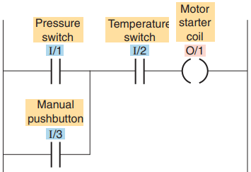
A typical ladder logic program for this process is shown in Figure 5 . The format used is similar to the layout of the hardwired relay ladder circuit. The individual symbols represent instructions, whereas the numbers represent the instruction location addresses.
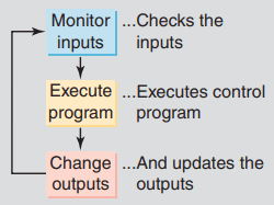
To program the controller, you enter these instructions one by one into the processor memory from the programming device. Each input and output device is given an address, which lets the PLC know where it is physically connected. Note that the I/O address format will differ, depending on the PLC model and manufacturer. Instructions are stored in the user program portion of the processor memory. During the program scan the controller monitors the inputs, executes the control program, and changes the output accordingly.
For the program to operate, the controller is placed in the RUN mode, or operating cycle. During each operating cycle, the controller examines the status of input devices, executes the user program, and changes outputs accordingly. Each symbol can be thought of as a set of normally open contacts. The symbol is considered to represent a coil that, when energized, will close a set of contacts.
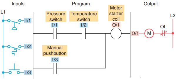
In the ladder logic program of Figure 5, the coil O/1 is energized when contacts I/1 and I/2 are closed or when contact I/3 is closed. Either of these conditions provides a continuous logic path from left to right across the rung that includes the coil. A programmable logic controller operates in real time in that an event taking place in the field will result in an operation or output taking place.
The RUN operation for the process control scheme can be described by the following sequence of events:
- First, the pressure switch, temperature switch, and pushbutton inputs are examined and their status is recorded in the controller’s memory.
- A closed contact is recorded in memory as logic 1 and an open contact as logic 0.
- Next the ladder diagram is evaluated, with each internal contact given an OPEN or CLOSED status according to its recorded 1 or 0 state.
- When the states of the input contacts provide logic continuity from left to right across the rung, the output coil memory location is given a logic 1 value and the output module interface contacts will close.
- When there is no logic continuity of the program rung, the output coil memory location is set to logic 0 and the output module interface contacts will be open.
- The completion of one cycle of this sequence by the controller is called a scan. The scan time, the time required for one full cycle, provides a measure of the speed of response of the PLC.
- Generally, the output memory location is updated during the scan but the actual output is not updated until the end of the program scan during the I/O scan. Figure 6 shows the typical wiring required to implement the process control scheme using a fixed PLC controller.
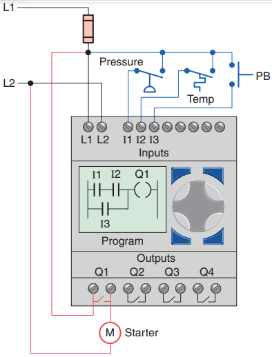
using a fixed PLC controller.
In this example the Allen-Bradley Pico controller equipped with 8 inputs and 4 outputs is used to control and monitor the process. Installation can be summarized as follows:
- Fused power lines, of the specified voltage type and level, are connected to the controller’s L1 and L2 terminals.
- The pressure switch, temperature switch, and pushbutton field input devices are hardwired between L1 and controller input terminals I1, I2, and I3, respectively.
- The motor starter coil connects directly to L2 and in series with Q1 relay output contacts to L1.
- The ladder logic program is entered using the front keypad and LCD display.
- Pico programming software is also available that allows you to create as well as test your program using a personal computer.
Modifying the Operation of PLC
One of the important features of a PLC is the ease with which the program can be changed. For example, assume that the original process control circuit for the mixing operation must be modified as shown in the relay ladder diagram of Figure 7.
The change requires that the manual pushbutton control be permitted to operate at any pressure, but not unless the specified temperature setting has been reached.
If a relay system were used, it would require some rewiring of the circuit shown in Figure 7 to achieve the desired change. However, if a PLC system were used, no rewiring would be necessary. The inputs and outputs are still the same. All that is required is to change the PLC ladder logic program as shown in Figure 8.
PLCs versus Computers
The architecture of a PLC is basically the same as that of a personal computer. A personal computer (PC) can be made to operate as a programmable logic controller if you provide some way for the computer to receive information from devices such as pushbuttons or switches. You also need a program to process the inputs and decide the means of turning load devices off and on. However, some important characteristics distinguish PLCs from personal computers.
First, unlike PCs, the PLC is designed to operate in the industrial environment with wide ranges of ambient temperature and humidity. A well-designed industrial PLC installation, is not usually affected by the electrical noise inherent in most industrial locations.
Unlike the personal computer, the PLC is programmed in relay ladder logic or other easily learned languages. The PLC comes with its program language built into its memory and has no permanently attached keyboard, CD drive, or monitor. Instead, PLCs come equipped with terminals for input and output field devices as well as communication ports.
Computers are complex computing machines capable of executing several programs or tasks simultaneously and in any order. Most PLCs, on the other hand, execute a single program in an orderly and sequential fashion from first to last instruction.
PLC control systems have been designed to be easily installed and maintained. Troubleshooting is simplified by the use of fault indicators and messaging displayed on the programmer screen. Input/output modules for connecting the field devices are easily connected and replaced.
Software associated with a PLC but written and run on a personal computer falls into the following two broad categories:
- PLC software that allows the user to program and document gives the user the tools to write a PLC program—using ladder logic or another programming language—and document or explain the program in as much detail as is necessary.
- PLC software that allows the user to monitor and control the process is also called a human machine interface (HMI). It enables the user to view a process—or a graphical representation of a process—on a monitor, determine how the system is running, trend values, and receive alarm conditions. Many operator interfaces do not use PLC software. PLCs can be integrated with HMIs but the same software does not program both devices.
Programmable Automation Controller (PAC)
Most recently automation manufacturers have responded to the increased requirements of industrial control systems by blending the advantages of PLC-style control with that of PC-based systems. Such a device has been termed a programmable automation controller, or PAC.
Programmable automation controllers combine PLC ruggedness with PC functionality. Using PACs, you can build advanced systems incorporating software capabilities such as advanced control, communication, data logging, and signal processing with rugged hardware performing logic, motion, process control, and vision.
Advantages of Programmable Logic Controllers
Programmable controllers offer several advantages over a conventional relay type of control. Relays have to be hardwired to perform a specific function. When the system requirements change, the relay wiring has to be changed or modified. In extreme cases, such as in the auto industry, complete control panels had to be replaced since it was not economically feasible to rewire the old panels with each model changeover.
The programmable controller has eliminated much of the hardwiring associated with conventional relay control circuits. It is small and inexpensive compared to equivalent relay-based process control systems. Modern control systems still include relays, but these are rarely used for logic. In addition to cost savings, PLCs provide many other benefits including:
1. Increased Reliability: Once a program has been written and tested, it can be easily downloaded to other PLCs. Since all the logic is contained in the PLC’s memory, there is no chance of making a logic wiring error. The program takes the place of much of the external wiring that would normally be required for control of a process. Hardwiring, though still required to connect field devices, is less intensive. PLCs also offer the reliability associated with solid-state components.
2. More Flexibility: It is easier to create and change a program in a PLC than to wire and rewire a circuit. With a PLC the relationships between the inputs and outputs are determined by the user program instead of the manner in which they are interconnected.
Original equipment manufacturers can provide system updates by simply sending out a new program. End users can modify the program in the field, or if desired, security can be provided by hardware features such as key locks and by software passwords.
3. Lower Cost: PLCs were originally designed to replace relay control logic, and the cost savings have been so significant that relay control is becoming obsolete except for power applications. Generally, if an application has more than about a half-dozen control relays, it will probably be less expensive to install a PLC.
4. Communications Capability: A PLC can communicate with other controllers or computer equipment to perform such functions as supervisory control, data gathering, monitoring devices and process parameters, and download and upload of programs.
5. Faster Response Time: PLCs are designed for high-speed and real-time applications. The programmable controller operates in real time, which means that an event taking place in the field will result in the execution of an operation or output. Machines that process thousands of items per second and objects that spend only a fraction of a second in front of a sensor require the PLC’s quick-response capability.
6. Easier to Troubleshoot: PLCs have resident diagnostics and override functions that allow users to easily trace and correct software and hardware problems. To find and fix problems, users can display the control program on a monitor and watch it in real time as it executes.
Thanks for reading about “introduction to programmable logic controllers.”
Your documentation is awesome. Really appreciated from the bottom of my heart