Parts of Programmable Logic Controller
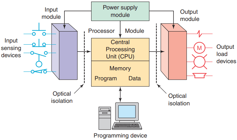
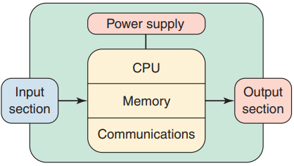
A typical PLC can be divided into parts, as illustrated in Figure 1. These are the central processing unit (CPU), the input/output (I/O) section, the power supply, and the programming device.
The term architecture can refer to PLC hardware, to PLC software, or to a combination of both. An open architecture design allows the system to be connected easily to devices and programs made by other manufacturers. Open architectures use off-the-shelf components that conform to approved standards.
A system with a closed architecture is one whose design is proprietary, making it more difficult to connect to other systems.
Most PLC systems are in fact proprietary, so you must be sure that any generic hardware or software you may use is compatible with your particular PLC. Also, although the principal concepts are the same in all methods of programming, there might be slight differences in addressing, memory allocation, retrieval, and data handling for different models. Consequently, PLC programs cannot be interchanged among different PLC manufacturers.
There are two ways in which I/Os (Inputs/Outputs) are incorporated into the PLC: fixed and modular.
Fixed I/O ( Figure 3 ) is typical of small PLCs that come in one package with no separate, removable units. The processor and I/O are packaged together, and the I/O terminals will have a fixed number of connections built in for inputs and outputs.
The main advantage of this type of packaging is lower cost. The number of available I/O points varies and usually can be expanded by buying additional units of fixed I/O.
One disadvantage of fixed I/O is its lack of flexibility; you are limited in what you can get in the quantities and types dictated by the packaging. Also, for some models, if any part in the unit fails, the whole unit has to be replaced.
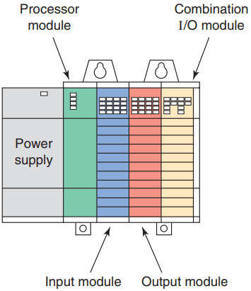
Modular I/O ( Figure 4 ) is divided by compartments into which separate modules can be plugged. This feature greatly increases your options and the unit’s flexibility. You can choose from the modules available from the manufacturer and mix them any way you desire.
The basic modular controller consists of a rack, power supply, processor module (CPU), input/output (I/O modules), and an operator interface for programming and monitoring. The modules plug into a rack. When a module is slid into the rack, it makes an electrical connection with a series of contacts called the backplane, located at the rear of the rack.
The PLC processor is also connected to the backplane and can communicate with all the modules in the rack. The power supply supplies DC power to other modules that plug into the rack.
For large PLC systems, this power supply does not normally supply power to the field devices. With larger systems, power to field devices is provided by external alternating current (AC) or direct current (DC) supplies. For some small micro PLC systems, the power supply may be used to power field devices.
The processor (CPU) is the “brain” of the PLC. A typical processor usually consists of a microprocessor for implementing the logic and controlling the communications among the modules. The processor requires memory for storing the results of the logical operations performed by the microprocessor.
Parts of Programmable Logic Controller
Memory is also required for the program EPROM or EEPROM plus RAM. The CPU controls all PLC activity and is designed so that the user can enter the desired program in relay ladder logic.
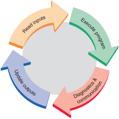
The PLC program is executed as part of a repetitive process referred to as a scan ( Figure 5 ). A typical PLC scan starts with the CPU reading the status of inputs. Then, the application program is executed. Once the program execution is completed, the CPU performs internal diagnostic and communication tasks. Next, the status of all outputs is updated. This process is repeated continuously as long as the PLC is in the run mode.
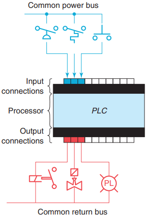
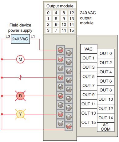
The I/O system forms the interface by which field devices are connected to the controller ( Figure 6 ). The purpose of this interface is to condition the various signals received from or sent to external field devices.
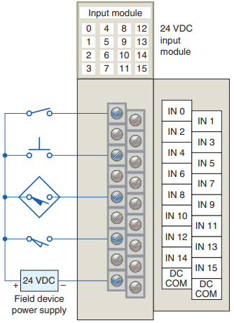
Input devices such as pushbuttons, limit switches, and sensors are hardwired to the input terminals. Output devices such as small motors, motor starters, solenoid valves, and indicator lights are hardwired to the output terminals. To electrically isolate the internal components from the input and output terminals, PLCs commonly employ an optical isolator, which uses light to couple the circuits together.
The external devices are also referred to as “field” or “real-world” inputs and outputs. The terms field or real world are used to distinguish actual external devices that exist and must be physically wired from the internal user program that duplicates the function of relays, timers, and counters.
A programming device is used to enter the desired program into the memory of the processor. The program can be entered using relay ladder logic, which is one of the most popular programming languages. Instead of words, ladder logic programming language uses graphic symbols that show their intended outcome.
A program in ladder logic is similar to a schematic for a relay control circuit. It is a special language written to make it easy for people familiar with relay logic control to program the PLC.
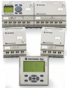
Hand-held programming devices are sometimes used to program small PLCs because they are inexpensive and easy to use. Once plugged into the PLC, they can be used to enter and monitor programs. Both compact hand-held units and laptop computers are frequently used on the factory floor for troubleshooting equipment, modifying programs, and transferring programs to multiple machines. A personal computer (PC) is the most commonly used programming device.
Most brands of PLCs have software available so that a PC can be used as the programming device. This software allows users to create, edit, document, store, and troubleshoot ladder logic programs.
The computer monitor is able to display more logic on the screen than can hand-held types, thus simplifying the interpretation of the program. The personal computer communicates with the PLC processor via a serial or parallel data communications link, or Ethernet.
If the programming unit is not in use, it may be unplugged and removed. Removing the programming unit will not affect the operation of the user program.
A program is a user-developed series of instructions that directs the PLC to execute actions. A programming language provides rules for combining the instructions so that they produce the desired actions.
Relay ladder logic (RLL) is the standard programming language used with PLCs. Its origin is based on electromechanical relay control. The relay ladder logic program graphically represents rungs of contacts, coils, and special instruction blocks. RLL was originally designed for easy use and understanding for its users and has been modified to keep up with the increasing demands of industry’s control needs.
PLC Size and Application
The criteria used in categorizing PLCs include functionality, number of inputs and outputs, cost, and physical size. Of these, the I/O count is the most important factor.
In general, the nano is the smallest size with less than 15 I/O points. This is followed by micro types (15 to 128 I/O points), medium types (128 to 512 I/O points), and large types (over 512 I/O points).
Matching the PLC with the application is a key factor in the selection process. In general it is not advisable to buy a PLC system that is larger than current needs dictate. However, future conditions should be anticipated to ensure that the system is the proper size to fill the current and possibly future requirements of an application. There are three major types of PLC application: single-ended, multitask, and control management.
A single-ended or stand-alone PLC application involves one PLC controlling one process. This would be a stand-alone unit and would not be used for communicating with other computers or PLCs. The size and sophistication of the process being controlled are obvious factors in determining which PLC to select. The applications could dictate a large processor, but usually this category requires a small PLC.
A multitask PLC application involves one PLC controlling several processes. Adequate I/O capacity is a significant factor in this type of installation. In addition, if the PLC would be a subsystem of a larger process and would have to communicate with a central PLC or computer, provisions for a data communications network are also required.
A control management PLC application involves one PLC controlling several others ( Figure 7 ). This kind of application requires a large PLC processor designed to communicate with other PLCs and possibly with a computer.
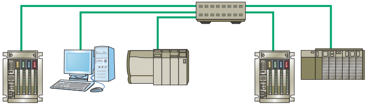
The control management PLC supervises several PLCs by downloading programs that tell the other PLCs what has to be done. It must be capable of connection to all the PLCs so that by proper addressing it can communicate with anyone it wishes to.
Memory is the part of a PLC that stores data, instructions, and the control program. Memory size is usually expressed in K values: 1 K, 6 K, 12 K, and so on. The measurement kilo, abbreviated K, normally refers to 1000 units. When dealing with computer or PLC memory, however, 1 K means 1024, because this measurement is based on the binary number system. Depending on memory type, 1 K can mean 1024 bits, 1024 bytes, or 1024 words.
Although it is common for us to measure the memory capacity of PLCs in words, we need to know the number of bits in each word before memory size can be accurately compared. Modern computers usually have a word size of 16, 32, or 64 bits.
For example, a PLC that uses 8-bit words has 49,152 bits of storage with a 6 K word capacity (8 x 6 x 1024 = 49,152), whereas a PLC using 32-bit words has 196,608 bits of storage with the same 6 K memory (32 x 6 x 1024 = 196,608).
The amount of memory required depends on the application. Factors affecting the memory size needed for a particular PLC installation include:
- Number of I/O points used
- Size of control program
- Data-collecting requirements
- Supervisory functions required
- Future expansion
The instruction set for a particular PLC lists the different types of instructions supported. Typically, this ranges from 15 instructions on smaller units up to 100 instructions on larger, more powerful units.
Thanks for reading about “Parts of Programmable Logic Controller”.