Entering Ladder Diagram
Most of today’s PLC programming packages operate in the Windows environment. For example, Allen-Bradley’s RSLogix software packages are Windows programming packages used to develop ladder logic programs. This software, in various versions, can be used to program the PLC-5, SLC 500, ControlLogix, and MicroLogic family of processors.
An added feature is that RSLogix programs are compatible with programs that have been previously created with DOS-based programming packages. You can import projects that were developed with DOS products or export to them from RSLogix.
Entering the ladder diagram, or actual programming, is usually accomplished with a computer keyboard or hand-held programming device. Because hardware and programming techniques vary with each manufacturer, it is necessary to refer to the programming manual for a specific PLC to determine how the instructions are entered.
One method of entering a program is through a handheld keyboard. Keyboards usually have relay symbol and special function keys along with numeric keys for addressing. Some also have alphanumeric keys (letters and numbers) for other special programming functions. In hand-held units, the keyboard is small and the keys have multiple functions. Multiple-function keys work like second-function keys on calculators.
A personal computer is most often used today as the programmer. The computer is adapted to the particular PLC model through the use of the relevant programmable controller software.
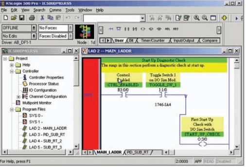
Figure 1 shows the RSLogix SLC 500 main window. Different screens, toolbars, and dialog boxes are used to navigate through the Windows environment. It is important that you understand the purpose of the various screens, toolbars, and windows to make the most effective use of the software. This information is available from the software reference manual for the particular PLC family and will become more familiar to you as you develop programs using the software.

Figure 2 shows a typical instruction toolbar with bit instructions selected. To place an instruction on a rung, click its icon on the toolbar and simply drag the instruction straight off the toolbar onto the rung of the ladder. Drop points are shown on the ladder to help position the instruction.
In addition, instructions can also be dragged from other rungs in the project. There are several different methods that you can use to address instructions. You can enter an address by manually typing it in or by dragging the address from data files or other instructions. Some of the windows you will need to use when working with RSLogix 500 software include:
Main Window: This window opens each time you create a new project or open an existing one. Some of the features associated with this window include the following: –
- Window Title Bar: The title bar is located at the topmost strip of the window and displays the name of the program as well as that of the opened file.
- Menu Bar: The menu bar is located below the title bar. The menu contains key words associated with menus that are opened by clicking on the key word.
- Windows Toolbar: The Windows toolbar buttons execute standard Windows commands when you click on them.
- Program/Processor Status Toolbar: This toolbar contains four drop-down lists that identify the current processor operating mode, current online edit status, and whether forces are present and enabled.
- Project Window: This window displays the file folders listed in the project tree.
- Project Tree: The project tree is a visual representation of all folders and their associated files contained in the current project. From the project tree, you can open files, create files, modify file parameters, copy files, hide or unhide files, delete files, and rename files.
- Result Window: This window displays the results of either a search or a verify operation. The verify operation is used to check the ladder program for errors.
- Active Tab: This tab identifies which program is currently active.
- Status Bar: This bar contains information relevant to the current file.
- Split Bar: The split bar is used to split the ladder window to display two different program files or groups of ladder rungs.
- Tabbed Instruction Toolbar: This toolbar displays the instruction set as a group of tabbed categories.
- Instruction Palette: This tool contains all the available instructions displayed in one table to make the selection of instructions easier.
- Ladder Window: This window displays the currently open ladder program file and is used to develop and edit ladder programs.
- Ladder Window Properties: This window allows you to change the display of your ladder program and its associated addressing and documentation.

Select Processor Type: The programming software needs to know what processor is being used in conjunction with the user program. The Select Processor Type screen ( Figure 3 ) contains a list of the different processors that the RSLogix software can program. You simply scroll down the list until you find the processor you are using and select it.

I/O Configuration: The I/O Configuration screen ( Figure 4 ) lets you click or drag-and-drop a module from an all-inclusive list to assign it to a slot in your configuration.
Data Files: Data File screens contain data that are used in conjunction with ladder program instructions and include input and output files as well as timer, counter, integer, and bit files. Figure 5 shows an example of the bit file B3, which is used for internal relays. Note that all the addresses from this file start with B3.

Relay ladder logic is a graphical programming language designed to closely represent the appearance of a wired relay system. It offers considerable advantages for PLC control. Not only is it reasonably intuitive, especially for users with relay experience, but it is also particularly effective in an online mode when the PLC is actually performing control. Operation of the logic is apparent from the highlighting of rungs of the various instructions on-screen, which identifies the logic state of contacts in real time ( Figure 6 ) and which rungs have logic continuity.

For most PLC systems, each Examine If Closed and Examine If Open contact, each output, and each branch Start/End instruction requires one word of user memory. You can refer to the SLC 500 Controller Properties to see the number of instruction words used and the number left as the program is being developed.
PLC Operation Modes
A processor has basically two modes of operation: the program mode and some variation of the run mode. The number of different operating modes and the method of accessing them varies with the manufacturer. Figure 7 shows a typical three-position keyswitch used to select different processor modes of operation. Some common operating modes are explained in the following paragraphs.

Program Mode: The program mode is used to enter a new program, edit or update an existing program, upload files, download files, document (print out) programs, or change any software configuration file in the program. When the PLC is switched into the program mode, all outputs from the PLC are forced off regardless of their rung logic status, and the ladder I/O scan sequence is halted.
Run Mode: The run mode is used to execute the user program. Input devices are monitored and output devices are energized accordingly. After all instructions have been entered in a new program or all changes made to an existing program, the processor is put in the run mode.
Test Mode: The test mode is used to operate or monitor the user program without energizing any outputs. The processor still reads inputs, executes the ladder program, and updates the output status table files, but without energizing the output circuits. This feature is often used after developing or editing a program to test the program execution before allowing the PLC to operate real-world outputs.
Variations of the test mode can include the single-step test mode, which directs the processor to execute a selected single rung or group of rungs; the single-scan test mode, which executes a single processor operating scan or cycle; and the continuous-scan test mode, which directs the processor to continuously run the program for checking or troubleshooting.
Remote Mode: Some processors have a three-position switch to change the processor operating mode. In the Run position, all logic is solved and the I/O is enabled. In the Program position, all logic solving is stopped and the I/O is disabled. The Remote position allows the PLC to be remotely changed between program and run mode by a personal computer connected to the PLC processor. The remote mode may be beneficial when the controller is in a location that is not easily accessible.