Method of Measuring Displacement, Velocity and Acceleration
Displacement is a quantity that indicates the change in position of a body or point. Angular displacement refers to a rotation that can be measured in degrees or radians. Displacement transducers can be either contacting or noncontacting. Contacting transducers typically use a sensing shaft with a coupling device to follow the position of the measured quantity.
Method of Measuring Displacement
A contacting type of displacement sensor that relates a change in inductance to displacement is the linear variable differential transformer (LVDT). The sensing shaft is connected to a moving magnetic core inside a specially wound transformer. A typical LVDT is shown in Figure 1(a).

The primary of the transformer is in line and located between two identical secondaries. The primary winding is excited with ac (usually in the range of 1 to 5 kHz). When the core is centered, the voltage induced in each secondary is equal.
As the core moves off center, the voltage in one secondary will be greater than the other. With the demodulator circuit shown, the polarity of the output changes as the core passes the center position, as shown in Figure 1(b). The transducer has excellent sensitivity, linearity, and repeatability.

Noncontacting displacement transducers include optical and capacitive transducers. Photocells can be arranged to observe light through holes in an encoding disk or to count fringes painted on the surface to be measured. Optical systems are fast; but noise, including background light sources, can produce spurious signals in optical sensors. It is useful to build hysteresis into the system if noise is a problem.
Fiber-optic sensors make excellent proximity detectors for close ranges. Reflective sensors use two fiber bundles, one for transmitting light and the other for receiving light from a reflective surface, as illustrated in Figure 2.
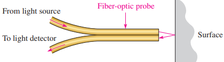
Light is transmitted in the fiber bundle without any significant attenuation. When it leaves the transmitting fiber bundle, it forms a spot on the target that is inversely proportional to the square of the distance. The receiving bundle is aimed at the spot and collects the reflected light to an optical sensor.
The light intensity detected by the receiving bundle depends on the physical size and arrangement of the fibers as well as the distance to the spot and the reflecting surface, but the technique can respond to distances approaching 1 microinch. The major disadvantage is limited dynamic range.
Capacitive sensors can be made into very sensitive displacement and proximity transducers. The capacitance is varied by moving one of the plates of a capacitor with respect to the second plate. The moving plate can be any metallic surface such as the diaphragm of a capacitive microphone or a surface that is being measured. The capacitor can be used to control the frequency of a resonant circuit to convert the capacitive change into a usable electrical output.
Method of Measuring Velocity
Velocity is defined as the rate of change of displacement. It follows that velocity can be determined indirectly with a displacement sensor and measuring the time between two positions. A direct measurement of velocity is possible with certain transducers that have an output proportional to the velocity to be measured.
These transducers can respond to either linear or angular velocity. Linear velocity transducers can be constructed using a permanent magnet inside a concentric coil, forming a simple motor by generating a voltage proportional to the velocity. Either the coil or the magnet can be fixed and the other moved with respect to the fixed component. The output is taken from the coil.
A variety of transducers are designed to measure angular velocity. Tachometers, a class of angular velocity transducers, provide a dc or ac voltage output. A dc tachometer is basically a small generator with a coil that rotates in a constant magnetic field. A voltage is induced in the coil as it rotates in the magnetic field.
The average value of the induced voltage is proportional to the speed of rotation, and the polarity is indicative of the direction of rotation, an advantage with dc tachometers.
AC tachometers can be designed as generators that provide an output frequency that is proportional to the rotational speed.
Another technique for measuring angular velocity is to rotate a shutter over a photosensitive element. The shutter interrupts a light source from reaching the photocells, causing the output of the photocells to vary at a rate proportional to the rotational speed.
Method of Measuring Acceleration
Acceleration is usually measured by use of a spring-supported seismic mass, mounted in a suitable enclosure as shown in Figure 3. Damping is provided by a dashpot, which is a mechanical device to reduce the vibration. The relative motion between the case and the mass is proportional to the acceleration.
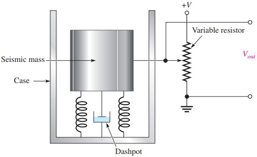
A secondary transducer such as a resistive displacement transducer or an LVDT is used to convert the relative motion to an electrical output. Ideally, the mass does not move when the case accelerates because of its inertia; in practice, it moves because of forces applied to it through the spring.
The accelerometer has a natural frequency, the period of which should be shorter than the time required for the measured acceleration to change. Accelerometers used to measure vibration should also be used at frequencies less than the natural frequency.
An accelerometer that uses the basic principle of the LVDT can be constructed to measure vibration. The mass is made from a magnet that is surrounded with a coil. Voltage induced in the coil is a function of the acceleration.
Another type of accelerometer uses a piezoelectric crystal in contact with the seismic mass. The crystal generates an output voltage in response to forces induced by the acceleration of the mass.
Piezoelectric crystals are small in size and have a natural frequency that is very high; they can be used to measure high-frequency vibration. The drawback to piezoelectric crystals is that the output is very low and the impedance of the crystal is high, making it subject to problems from noise.