This article explains how the PLC shift register functions operate and how it can be applied to control problems. Shift registers are often used to track parts on automated manufacturing lines by shifting either status or values through data files.
PLC Shift Register Instructions & Programs
The PLC not only uses a fixed pattern of register (word) bits, but also can easily manipulate and change individual bits. A bit shift register is a register that allows the shifting of bits through a single register or group of registers. The bit shift register shifts bits serially (from bit to bit) through an array in an orderly fashion.
A shift register can be used to simulate the movement, or track the flow, of parts and information. We use the shift register whenever we need to store the status of an event so that we can act on it at a later time. Shift registers can shift either status or values through data files. Common applications for shift registers include the following:
- Tracking of parts through an assembly line
- Controlling of machine or process operations
- Inventory control
- System diagnostics
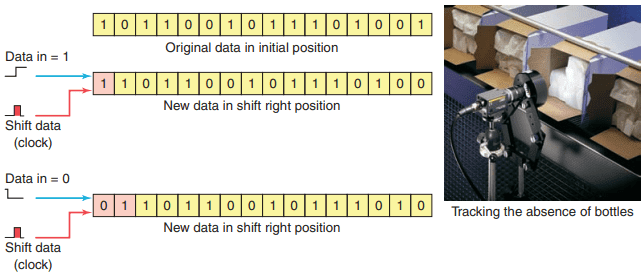
Figure 1 illustrates the basic concept of a shift register. A shift pulse or clock causes each bit in the shift register to move 1 position to the right. At some point, the number of data bits fed into the shift register will exceed the register’s storage capacity.
When this happens, the first data bits fed into the shift register by the shift pulse are lost at the end of the shift register. Typically, data in the shift register could represent the following:
- Part types, quality, and size
- The presence or absence of parts
- The order in which events occur
- Identification numbers or locations
- A fault condition that caused a shutdown

You can program a shift register to shift status data either right or left, as illustrated in Figure 2, by shifting either status or values through data files. When you want to track parts on a status basis, use bit shift registers. Bit shift instructions will shift bit status from a source bit address, through a data file, and out to an unload bit, one bit at a time.
There are two bit shift instructions: bit shift left (BSL), which shifts bit status from a lower address number to a higher address number through a data file, and bit shift right (BSR), which shifts data from a higher address number to a lower address number through a data file.
Some PLCs provide a circulating shift register function, which allows you to repeat a pattern again and again. When working with a bit shift register, you can identify each bit by its position in the register. Therefore, working with any bit in the register becomes a matter of identifying the position it occupies rather than the conventional word number/bit number addressing scheme.
PLC Shift Register Instructions & Programs

Figure 3 shows the File Shift menu tab and BSL and BSR instruction blocks that are part of the instruction set for the Allen-Bradley SLC 500 controllers. The commands can be summarized as follows:
- BSL (Bit Shift Left) —Loads a bit of data into a bit array, shifts the pattern of data through the array to the left, and unloads the last bit of data in the array.
- BSR (Bit Shift Right) —Loads a bit of data into a bit array, shifts the pattern of data through the array to the right, and unloads the last bit of data in the array.
Shift registers are useful for tracking the status or identification of a part as it moves down an assembly line. The data file used for a shift register usually is the bit file because its data are displayed in binary format, making it easier to read. BSL and BSR are output instructions that load data into a bit array one bit at a time. The data are shifted through the array, then unloaded one bit at a time.
The BSL instruction has the same operands as the BSR instruction. The difference is the direction in which the bits are indexed. A bit shift instruction will execute when its input control logic goes from false to true. To program a bit shift instruction, you need to provide the processor with the following information:
- File —The address of the bit array you want to manipulate. The address must start with the # sign and at bit 0 of the first word or element. Any remaining bits in the last word of the array cannot be used elsewhere in the program because the instruction invalidates them.
- Control —R data-table type. The address is unique to the instruction and cannot be used to control any other instruction. It is a three-word element that consists of the status word, the length, and the position.
- Bit address —Is the address of the source bit. The instruction inserts the status of this bit in either the first (lowest) bit position (for the BSL instruction) or the last (highest) bit position (for the BSR instruction) in the array.
Length —Indicates the number of bits to be shifted, or the file length, in bits. The status bits of the control word are the enable, done, error, and unload bits. Their functions can be summarized as follows:
- Enable Bit (EN) —The enable bit follows the instructions status and is set to 1 when the instruction is true.
- Done Bit (DN) —The done bit is set to 1 when the instruction has shifted all bits in the file one position. It resets to 0 when the instruction goes false.
- Error Bit (ER) —The error bit is set to 1 when the instruction has detected an error, which can happen when a negative number is entered in the length.
- Unload Bit (UL) —The unload bit’s status is controlled by shifting of the last bit of the file into the unload bit when the instruction is executed. It is the bit location into which the status from the last bit in the file shifts when the instruction goes from false to true. When the next shift occurs, these data are lost, unless additional programming is done to retain the data.


An example of a bit shift left (BSL) instruction program is shown in Figure 4. The operation of the program can be summarized as follows:
- Momentary actuation of limit switch LS causes the BSL instruction to execute.
- When the rung goes from false to true, the enable bit is set and the data block is shifted to the left (to a higher bit number) one bit position.
- The specified bit, at sensor bit address I:1/1, is shifted into the first bit position, B3:10/0.
- The last bit is shifted out of the array and stored in the unload bit, R6:0/UL.
- The status that was previously in the unload bit is lost.
- All the bits in the unused portion of the last word of the file are invalid and should not be used elsewhere in the program.
- For wraparound operation, set the position of the bit address to the last bit of the array or to the UL bit, whichever applies.

An example of a bit shift right (BSR) instruction program is shown in Figure 5. The operation of the program can be summarized as follows:
- Before the rung goes from false to true, the status of bits in words B3:50 and B3:51 is as shown.
- The status of the bit address, I:3/5, is a 0, and the status of the unload bit, R6:1/UL, is a 1.
- When limit switch LS closes, the status of the bit address, I:3/5, is shifted into B3:51/7, which is the 24th bit in the file.
- The status of all the bits in the file is shifted one position to the right, through the length of 24 bits.
- The status of B3:50/0 is shifted to the unload bit, R6:1/UL. The status that was previously in the unload bit is lost.

An example of a bit BSL instruction program with wraparound operation is shown in Figure 6. The clock pulse input is a fixed regular 3 second pulse–generated on-delay timer T4:0. The operation of the program can be summarized as follows:
- Go to the data tables and set bit addresses B3:0/0, B3:0/1, B3:0/2 to logic 0 and bit address R6:0/UL to logic 1.
- When the PLC is then placed in run, bit B3:0/0 is set to logic 1 causing PL1 to turn on.
- Closing input switch SW starts timer T4:0 timing.
- After 3 seconds the timer done bit is set to reset the timer accumulated time to zero and shift the logic bit 1 to the left to B3:0/1.
- This causes PL1 to turn off and PL2 to turn on.
- After another 3 seconds, the timer done bit is set once again.
- The BSL instruction shifts the bits to the left once more and causes PL2 to turn off and PL3 to turn on.
- The process continues with each of the pilot lights turned on in sequence for 3 seconds.
A shift register is often used in material handling processes where some form of binary information must be synchronized with a moving part on a conveyor. The binary information refers to any two conditions that can be assigned to the moving product—for example, the presence or absence of a part. As the part moves along the conveyer, some form of sensing device will determine which of these two categories the passing product falls into.

Figure 7 illustrates cartons traveling on a conveyor being detected by a photoelectric sensor. The sensor that drives the data line on a shift register is fixed such that the beam detects the presence or absence of a carton. A logic 1 sensor condition state can indicate the presence of a carton, and a 0 the absence.

The process of Figure 8 illustrates a spray-painting operation controlled by a shift left register. As the parts pass along the production line, the shift register bit patterns represent the items on the conveyor hangers to be painted. Each file bit location represents a station on the line, and the status of the bit indicates whether or not a part is present at that station.

The program for the spray-painting operation is shown in Figure 9. Its operation can be summarized as follows:
- Limit switch LS1 is used to detect the hanger and limit switch LS2 the part.
- The pulse generated by the hanger-operated limit switch LS1 shifts the status of the data provided by part-detection limit switch LS2.
- The logic of this operation is such that when a part to be painted and a part hanger occur together at station 1 (indicated by simultaneous closing of LS2 and by LS1), logic 1 is input into the shift register at B3:0/0.
- This causes the SOL 1 rung to be true and the undercoat spray gun to energize.
- At station 5 a 1 appears in bit B3:0/5 of the shift register to make the SOL 2 rung true and topcoat spray gun energize.
- Logic 0 in the shift register indicates that the conveyor has no parts on it to be sprayed, and it therefore inhibits the operation of the spray guns.
- Counter C5:1 counts the parts as they enter the process and counter C5:2 as they exit.
- The count obtained by the two counters should be equal when no parts are being painted.
- Whenever the two counts are equal in value the equal instruction executes to turn on pilot light PL1. This is an indication that the parts commencing the spray painting run equal the parts that have completed it.


An example for a bit shift program used to keep track of carriers flowing through a 16-station machine is shown Figure 10. The operation of the program can be summarized as follows:
- Proximity switch 1 senses a carrier, and proximity switch 2 senses a part on the carrier.
- Clock pulse generated by carrier proximity switch I:1/1 shifts the status of the data provided by part detection proximity switch I:1/2.
- When a part and container are sensed together, indicated by simultaneous closing of I:1/2 and I:1/1; logic 1 is input into the shift register at output O4:0/0 to energize the pilot light connected to it.
- Remaining pilot lights connected to output module O:4 turn on in sequence as carriers with parts move through each station.
- They turn off or remain off as empty carriers move through.
- Station 5 is an inspection station where parts are examined.
- If the part fails, the inspectors push PB1 as they remove the part from the system, which turns output O:4/4 off.
- Rework parts can be added back into the system at station 7.
- When the operator puts a part on an empty carrier, he or she pushes PB2, turning output O:4/6 on to resume tracking.
Word Shift Operations
The first in, first out (FIFO) instructions are word shift operations that are similar to bit shift operations. Word shifting provides a simpler method of loading and unloading data into a file, usually called the stack. It is often used for tracking parts through an assembly line, where parts are represented by values that have a part number or an assembly code.
A bit shift register operates synchronously or in a serial fashion because information is shifted one bit at a time within a word or words. For every bit shifted in, one is shifted out. Data entered in a bit shift register must be shifted the length of the register (one position per shift pulse) before they are available to shift out.
A FIFO function operates asynchronously. Rather than shifting bits of information within a word it shifts the data from a complete word into a file or stack. Unlike the bit shift register, two separate shift pulses are required: one to shift data into the file (load) and one to shift data out of the file (unload). These two shift pulses operate independently (asynchronously) of each other. Data loaded in a FIFO can be immediately available for unload, regardless of length.
The FFL and FFU instruction are used in pairs. The FFL loads logic words into a user-created file called a FIFO stack. The FFU instruction is used to unload the words from the FIFO stack, in the same order as the words were entered. The first word entered is the first word out. The SLC 500 FIFO load (FFL) instruction is shown in Figure 11.

The parameters that are required to be entered in the instruction block are summarized as follows:
- Source —Word address from which the data are entered into the FIFO file.
- FIFO —Address of the file in which the data are entered. The address must start with a # sign.
- Control —R data-table type and is the file address of the control structure. The status bits, stack length, and position are stored in this element.
- Length —File length in words. Specifies the maximum number of words in the stack.
- Position —Is the next available location where the instruction loads data into the stack. The first address in the stack is position 0. As each word is entered into the stack, the position counter, on both the FFL and FFU, will increment up by one. The stack is considered full when the position value equals the length. The status bits of the control word are the enable (EN), the done (DN), and the empty (EM) bits. Their functions can be summarized as follows:
– Enable Bit (EN) —The enable bit follows the instructions status and is set to 1 when the instruction is true.
– Done Bit (DN) —The done bit is set to 1when the instruction’s position equals the length. When the done bit is set, the FIFO is full and does not accept any more data. Also the data in the FIFO file are not overwritten when the instruction goes from false to true.
– Empty Bit (EM) —The empty bit is set to 1 when all the data have been unloaded from the FIFO file.

Figure 12 shows the SLC 500 FIFO unload (FFU) instruction. The following parameters need to be entered in the SLC 500 FFU instruction:
- FIFO —Address of the file in which the data are entered. The address must start with a # sign. When paired with an FFL instruction, this address is the same as the address for the FFL.
- Destination —Address to which the FFU unloads data.
- Control —R data-table type. It is a three-word element that consists of the status word, the length, and the position. When it is paired with the FFL, the control addresses are the same.
- Length —File length in words. Specifies the maximum number of words in the stack.
- Position —Next location from which data are unloaded when the instruction goes from false to true. The status bits of the control word are the enable (EN), the done (DN), and the empty (EM) bits. The enable bit follows the instruction’s status, the done bit is set when the instruction’s position equals the length, and the empty bit is set when all the data have been unloaded from the FIFO file.


The program of Figure 13 is an example of how data are indexed in and out of a FIFO file using the FFL and FFU instruction pair. The operation of the program can be summarized as follows:
- The FIFO load and FIFO unload instructions share the same control element, R6:0, which may not be used to control any other instructions.
- FIFO, #N7:12, is the address of the stack. The same address is programmed for the FFL and FFU instructions.
- Data enter the FIFO file from the source address, N7:10, on a false-to-true transition of input A.
- Data are placed at the position indicated in the instruction on a false-to-true transition of the FFL instruction, after which the position indicates the current number of data entries in the FIFO file.
- The FIFO file fills from the beginning address of the FIFO file and indexes to one higher address for each false-to-true transition of input A.
- A false-to-true transition of input B causes all data in the FIFO file to shift one position toward the starting address of the file, with the data from the starting address of the file shifting to the destination address, N7:11.
The FIFO instruction is often used for inventory control. One example is where different parts need to be removed from inventory to be used in production. Each part is assigned a unique code, which is loaded into a FIFO stack, and parts are removed in the order prescribed by the stack. This type of control ensures that the oldest part in the inventory is used first as the first part entered is the first part removed.
The opposite principle—where the last data to be stored are the first to be retrieved—is known as LIFO (Last In, First Out). The LIFO instruction inverts the order of the data it receives by outputting the last data received first and the first data received last.

A useful analogy is a pile of work on your desk. As new work arrives you drop it on the top of the stack. If your stack is LIFO, you pick your next job from the top of the pile. If your stack is FIFO, you pick your work from the bottom of the pile. Figure 14 shows how the FIFO and LIFO operations work for container stacking operations.

The difference between FIFO and LIFO stack operation is that the LIFO instruction removes data in the reverse of the order they are loaded (last in, first out). An example of the LIFO instruction pair is shown in Figure 15 and the operation of this function can be summarized as follows:
- The load and unload of the LIFO stack operates similarly to that of the FIFO stack, except that the last word in the LIFO stack is the first word that is unloaded from the stack.
- Words can be added to the LIFO stack without disturbing the words already loaded on the stack.
- Otherwise, LIFO instructions operate the same as FIFO instructions.