Troubleshooting of PLC
In the event of a PLC fault, you should employ a careful and systematic approach to troubleshoot the system to resolve the problem. PLCs are relatively easy to troubleshoot because the control program can be displayed on a monitor and watched in real time as it executes.
If a control system has been operating, you can be fairly confident of the accuracy of the program logic. For a system that has never worked or is just being commissioned, programming errors should be considered.
When a problem occurs, the first step in the troubleshooting procedure is to identify the problem and its source. The source of a problem can generally be narrowed down to the processor module, I/O hardware, wiring, machine inputs or outputs, or ladder logic program.
Once a problem is recognized, it is usually quite simple to deal with. The following sections will deal with troubleshooting these potential problem areas.
Troubleshooting of PLC
Processor Module
The processor is responsible for the self-detection of potential problems. It performs error checks during its operation and sends status information to indicators that are normally located on the front of the processor module. You can diagnose processor faults or obtain more detailed information about the processor by accessing the processor status through programming software.

Figure 1 shows sample diagnostics LEDs found on a processor module. What they indicate can be summarized as follows:
RUN (Green)
- On steady indicates that the process is in the RUN mode.
- Flashing during operation indicates that the process is transferring a program from RAM to the memory module.
- Off indicates that processor is in a mode other than RUN.
FLT (Red)
- Flashing at power-up indicates that the processor has not been configured.
- Flashing during operation indicates a major error either in the processor, chassis, or memory.
- On steady indicates that a fatal error is present (no communications).
- Off indicates there are no errors.
BATT (Red)
- On steady indicates the battery voltage has fallen below a threshold level, or the battery is missing or not connected.
- Off indicates that the battery is functional.
The processor then monitors itself continually for any problems that might cause the controller to execute the user program improperly. Depending on the controller, a set of fault relay contacts may be available. The fault relay is controlled by the processor and is activated when one or more specific fault conditions occur. The fault relay contacts are used to disable the outputs and signal a failure.
Most PLCs incorporate a watchdog timer to monitor the scan process of the system. The watchdog timer is usually a separate timing circuit that must be set and reset by the processor within a predetermined period.
The watchdog timer circuit monitors how long it takes the CPU to complete a scan. If the CPU scan takes too long, a watchdog major error will be declared. PLC user manuals will show how to apply this function.
The PLC processor hardware is not likely to fail because today’s microprocessors and microcomputer hardware are very reliable when operated within the stated limits of temperature, moisture, and so on.
The PLC processor chassis is typically designed to withstand harsh environments.
Input Malfunctions
If the controller is operating in the RUN mode but output devices do not operate as programmed, the faults could be associated with any of the following:
- Input and output wiring between field devices and modules
- Field device or module power supplies
- Input sensing devices
- Output actuators
- PLC I/O modules
- PLC processor
Narrowing down the problem source can usually be accomplished by comparing the actual status of the suspect I/O with controller status indicators. Usually each input or output device has at least two status indicators. One of these indicators is on the I/O module; the other indicator is provided by the programming device monitor.

The circuit of Figure 2 illustrates how to check for discrete input malfunctions. The steps taken can be summarized as follows:
- When input hardware is suspected to be the source of a problem, the first check is to see if the status indicator on the input module illuminates when it is receiving power from its corresponding input device (e.g., pushbutton, limit switch).
- If the status indicator on the input module does not illuminate when the input device is on, take a voltage measurement across the input terminal to check for the proper voltage level.
- If the voltage level is correct, then the input module should be replaced.
- If the voltage level is not correct, power supply, wiring, or input device may be faulty.
If the programming device monitor does not show the correct status indication for a condition instruction, the input module may not be converting the input signal properly to the logic level voltage required by the processor module. In this case, the input module should be replaced. If a replacement module does not eliminate the problem and wiring is assumed to be correct, then the I/O rack, communication cable, or processor should be suspected.

Figure 3 shows a typical input device troubleshooting guide. This guide reviews condition instructions and how their true/false status relates to external input devices.
Output Malfunctions
In addition to the logic indicator, some output modules incorporate either a blown fuse indicator or a power indicator or both. A blown fuse indicator indicates the status of the protective fuse in the output circuit, while a power indicator shows that power is being applied to the load.

Electronic protection, as shown in Figure 4, is also used to provide protection for the modules from short-circuit and overload current conditions. The protection is based on a thermal cut-out principle. In the event of a short-circuit or overload current condition on an output channel, that channel will limit current within milliseconds after its thermal cut-out temperature has been reached. All other channels continue to operate as directed by the processor.
When an output does not energize as expected, first check the output module blown fuse indicator. Many output modules have each output fused. This indicator will normally illuminate only when the output circuit corresponding to the blown fuse is energized. If this indicator is illuminated, correct the cause of the malfunction and replace the blown fuse in the module.

Figure 5 shows a typical discrete output module troubleshooting guide. In general, the following items should be noted when troubleshooting discrete output modules:
- If the blown fuse indicator is not illuminated (fuse OK), then check to see if the output device is responding to the LED status indicator.
- An output module’s logic status indicator functions similarly to an input module’s status indicator. When it is on, the status LED indicates that the module’s logic circuitry has recognized a command from the processor to turn on.
- If an output rung is energized, the module status indicator is on, and the output device is not responding, then the wiring to the output device or the output device itself should be suspected.
- If, according to the programming device monitor, an output device is commanded to turn on but the status indicator is off, then the output module or processors may be at fault.
- Check voltage at output; if incorrect, power supply, wiring, or output device may be faulty.
Ladder Logic Program
Many PLC software programs offer various software checks used to verify program logic. Figure 6 shows a sample of verifying program errors using RSLogix 500 software.

Selecting edit then verify project will check the program for errors. The sample shows what the error message might look like. The ladder logic program itself is not likely to fail, assuming that the program was at one time working correctly. A hardware fault in the memory IC that holds the ladder logic program could alter the program, but this is a PLC hardware failure.
If all other possible sources of trouble have been eliminated, the ladder logic program should be reloaded into the PLC from the master copy of the program. Make sure the master copy of the program is up to date before you download it to the PLC. Start program troubleshooting by identifying which outputs operate properly and which outputs do not.
Then trace back from the output on the non-functioning rung and examine the logic to determine what may be preventing the output from energizing. Common logic errors include:
- Programming an examine if closed instruction instead of an examine if open (or vice versa)
- Using an incorrect address in the program
Although the ladder logic program is not likely to fail, the process may be in a state that was unaccounted for in the original program and thus is not controlled properly. In this case, the program needs to be modified to include this new state.
A careful examination of the description of the control system and the ladder logic program can help identify this type of fault. The force on and force off instructions allow you to turn specific bits on or off for testing purposes.

Figure 7 illustrates how forces are identified as being enabled or disabled in RSLogix 500 software. Forcing lets you simulate operation or control an output device. For example, forcing a solenoid valve on will tell you immediately whether the solenoid is functional when the program is bypassed. If it is, the problem must be related to the software and not the hardware.
If the output fails to respond when forced, either the actual output module is causing the problem or the solenoid itself is malfunctioning. Take all necessary precautions to protect personnel and equipment during forcing.

Certain diagnostic instructions may be included as part of a PLC’s instruction set for troubleshooting purposes. The temporary end (TND) instruction, shown in Figure 8, is used when you want to change the amount of logic scanned to progressively debug your program. The operation of this output instruction can be summarized as follows:
- The instruction operates only when its rung conditions are true and stops the processor from scanning any logic beyond the TND instruction.
- When the processor encounters a true TND rung, it resets the watchdog timer (to 0), performs an I/O update, and begins running the ladder program at the first instruction in the main program.
- If the TND rung is false, the processor continues the scan until the next TND instruction or the END statement.
- By inserting the TND instruction at different locations in the program you can test parts of the program sequentially until the entire program has been tested.
- Once the troubleshooting process has been completed, any remaining TND instructions are removed from the program.

The suspend (SUS) instruction, shown in Figure 9, is used to trap and identify specific conditions for program debugging and system troubleshooting. The operation of this output instruction can be summarized as follows:
- When the rung is true, this instruction places the controller in the suspend or idle mode.
- The suspend ID, in this case 100, must be selected by the programmer and entered in the instruction.
- When the SUS instruction executes, the ID number 100 is written in word 7 (S:7) of the status file.
- If multiple suspend instructions are present, then this will indicate which SUS instruction was active.
- The suspend file (program or subroutine number identifying where the executed SUS instruction resides) is placed in word 8 (S:8) of the status file.
- All ladder logic outputs are de-energized, but other status files have the data present when the suspend instruction was executed.
Most PLC system faults occur in the field wiring and devices. The wiring between the field devices and the terminals of the I/O modules is a likely place for problems to occur. Faulty wiring and mechanical connection problems can interrupt or short the signals sent to and from the I/O modules. The sensors and actuators connected to the I/O of the process can also fail. Mechanical switches can wear out or be damaged during normal operation. Motors, heaters, lights, and sensors can also fail.
Input and output field devices must be compatible with the I/O module to ensure proper operation. When an instruction does not seem to be working correctly, the problem may be an addressing conflict caused by the same address being used for two or more coil instructions in the same program. As a result, multiple rung conditions can control the same output coil, making troubleshooting more difficult. In the case of duplicate outputs, the monitored rung may be true; but if a rung farther down in the ladder diagram is false, the PLC will keep the output off.

The program of Figure 10 illustrates what happens when the same address is used for two coils. The resulting problem scenario can be summarized as follows:
- The problem is turning input switch I:1/1 on will not turn on PL output O:2/1 as it appears to be programmed.
- The root of the problem lies in the fact that the PLC scans the program from left to right and top to bottom.
- Whenever input switch I:1/1 is true (closed) and input switch I:1/2 is false (open) output O:2/1 will be off.
- This is because when the PLC updates the outputs it does so based on the status of input I:1/2.
- Regardless of whether input I:1/1 is open or closed the output reacts only to the status of input switch I:1/2.
When a problem occurs, the best way to proceed is to try to logically identify the devices or connections that could be causing the problem rather than arbitrarily checking every connection, switch, motor, sensor, I/O module, and so on. First, observe the system in operation and try to describe the problem.

Using these observations and the description of the control system, you should identify the possible sources of trouble. Compare the logic status of the hardwired inputs and outputs to their actual state, as illustrated in Figure 11.
Any disagreements indicate malfunctions as well as their approximate location. Some of your troubleshooting can be accomplished by interpreting the status indicators on the I/O modules. The key is to know whether the status indicators are telling you that there is a fault or that the system is normal. Often PLC manufacturers supply a troubleshooting guide, map, or tree that presents a list of observed problems and their possible sources.
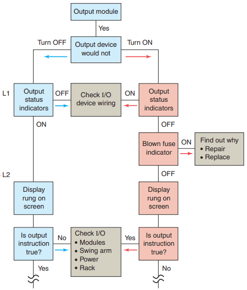

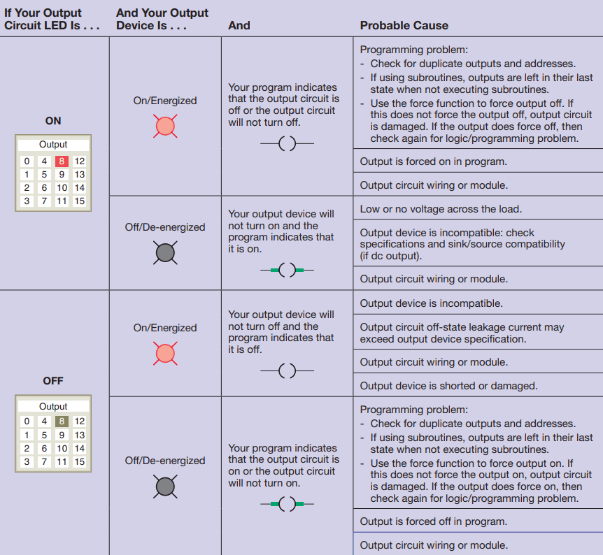
Figure 12 shows a sample troubleshooting tree for a discrete output module. Figures 13 and 14 are samples of input and output troubleshooting guides.
PLC Programming Software
You must establish a way for your personal computer (PC) software to communicate with the programmable logic controller (PLC) processor. Making this connection is known as configuring the communications.
The method used to configure the communications varies with each brand of controller. In Allen-Bradley controllers, RSLogix software is required to develop and edit ladder programs. A second software package, RSLinx, is needed to monitor PLC activity, download a program from your PC to your PLC, and upload a program from your PLC into your PC.
You cannot download multiple projects to the PLC and then run them when required. The PLC will accept only one program at a time, but the program can consist of multiple subroutine files which can be conditionally called from the main program.
RSLinx software is available in multiple packages to meet the demand for a variety of cost and functionality requirements. This software package is used as the driver between your PC and PLC processor.
A driver is a computer program that controls a device. For example, you must have the correct printer driver installed in your PC in order to be able to print a word-processing document created on your PC. RSLinx works much like the printer driver for RSLogix software. The RSLinx program must be opened and drivers configured before communications can be established between a PC and a PLC that is using RSLogix software.
RSLinx allows RSLogix to communicate through an interface cable to the PLC processor. The simplest connection between a PC and a PLC is a point-to-point direct connection through the computer serial port, as illustrated in Figure 15.

A serial cable is used to connect to your PC’s COM 1 or COM 2 port and to the PLC processor’s serial communications port. With RSLinx software you can auto-configure the serial connection and thus automatically find the proper serial port configuration.
Two important aspects of the communication link must be considered, namely, the RS-232 standard and the communications protocol. The RS-232 standard specifies a function for each of the wires inside the standard communications cable and their associated pins.
Communications protocol is a standardized method for transmitting data and/or establishing communications between different devices. Minimum configuration for two-way communications requires the use of only three connected wires, as shown in Figure 16.

For ease of connection, the RS-232 standard specifies that computer devices have male connectors and that peripheral equipment have female connectors. Direct communication between two computers, such as a PC and a PLC, does not involve intermediate peripheral equipment. Therefore, a serial null-modem type cable must be used for the connection because both the PC and the PLC processor use pin 2 for data output and pin 3 for data input.