Generating and Braking of Induction Motor
Having explored the torque–speed curve for the normal motoring region, where the speed lies between zero and just below synchronous, we must ask what happens if the speed is above the synchronous speed, or is negative. A typical torque–speed curve for a cage motor covering the full range of speeds, which are likely to be encountered in practice, is shown in Figure 1.
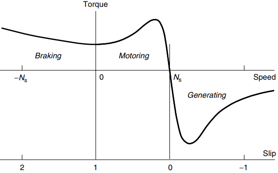
We can see from Figure 1 that the decisive factor as far as the direction of the torque is concerned is the slip, rather than the speed. When the slip is positive the torque is positive, and vice versa. The torque therefore always acts so as to urge the rotor to run at zero slip, i.e. at the synchronous speed.
If the rotor is tempted to run faster than the field it will be slowed down, whilst if it is running below synchronous speed it will be urged to accelerate forwards. In particular, we note that for slips greater than 1, i.e. when the rotor is running backwards (i.e. in the opposite direction to the field), the torque will remain positive, so that if the rotor is unrestrained it will first slow down and then change direction and accelerate in the direction of the Weld.
Generating Region – Overhauling Loads
For negative slips, i.e. when the rotor is turning in the same direction, but at a higher speed than the travelling field, the ‘motor’ torque is in fact negative. In other words the machine develops a torque that which opposes the rotation, which can therefore only be maintained by applying a driving torque to the shaft. In this region the machine acts as an induction generator, converting mechanical power from the shaft into electrical power into the supply system.
Many cage induction machines are used in this way in wind power generation schemes because their inherently robust construction leads to low maintenance. It is worth stressing that, just as with the d.c. machine, we do not have to make any changes to an induction motor to turn it into an induction generator. All that is needed is a source of mechanical power to turn the rotor faster than the synchronous speed.
On the other hand, we should be clear that the machine can only generate when it is connected to the supply. If we disconnect an induction motor from the mains and try to make it generate simply by turning the rotor we will not get any output because there is nothing to set up the working flux: the flux (excitation) is not present until the motor is supplied with magnetising current from the supply.
There are comparatively few applications in which mains-fed motors find themselves in the generating region, though as we will see later it is quite common in inverter-fed drives. We will, however, look at one example of a mains-fed motor in the so-called ‘regenerative’ mode to underline the value of the motor’s inherent ability to switch from motoring to generating automatically, without the need for any external intervention.
Consider a cage motor driving a simple hoist through a reduction gearbox, and suppose that the hook (unloaded) is to be lowered. Because of the static friction in the system, the hook will not descend on its own, even after the brake is lifted, so on pressing the ‘down’ button the brake is lifted and power is applied to the motor so that it rotates in the lowering direction. The motor quickly reaches full speed and the hook descends.
As more and more rope winds off the drum, a point is reached where the lowering torque exerted by the hook and rope is greater than the running friction, and a restraining torque is then needed to prevent a runaway. The necessary stabilising torque is automatically provided by the motor acting as a generator as soon as the synchronous speed is exceeded, as shown in Figure 1.
The speed will therefore be held at just above the synchronous speed, provided of course that the peak generating torque (see Figure 1) is not exceeded.
Plug Reversal and Plug Braking
Because the rotor always tries to catch up with the rotating field, it can be reversed rapidly simply by interchanging any two of the supply leads. The changeover is usually obtained by having two separate 3-pole contactors, one for forward and one for reverse. This procedure is known as plug reversal or plugging, and is illustrated in Figure 2.
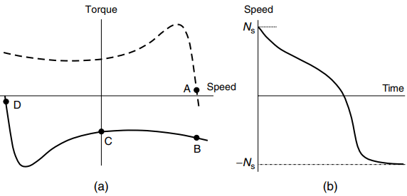
The motor is initially assumed to be running light (and therefore with a very small positive slip) as indicated by point A on the dotted torque– speed curve in Figure 2(a). Two of the supply leads are then reversed, thereby reversing the direction of the field, and bringing the mirror-image torque–speed curve shown by the solid line into play. The slip of the motor immediately after reversal is approximately 2, as shown by point B on the solid curve.
The torque is thus negative, and the motor decelerates, the speed passing through zero at point C and then rising in the reverse direction before settling at point D, just below the synchronous speed. The speed–time curve is shown in Figure 2(b).
We can see that the deceleration (i.e. the gradient of the speed–time graph) reaches a maximum as the motor passes through the peak torque (pullout) point, but thereafter the final speed is approached gradually, as the torque tapers down to point D.
Very rapid reversal is possible using plugging; for example a 1 kW motor will typically reverse from full speed in under 1 s. But large cage motors can only be plugged if the supply can withstand the very high currents involved, which are even larger than when starting from rest.
Frequent plugging will also cause serious overheating, because each reversal involves the ‘dumping’ of four times the stored kinetic energy as heat in the windings.
Plugging can also be used to stop the rotor quickly, but obviously it is then necessary to disconnect the supply when the rotor comes to rest, otherwise it will run-up to speed in reverse. A shaft-mounted reverse-rotation detector is therefore used to trip out the reverse contactor when the speed reaches zero.
We should note that, whereas, in the regenerative mode the slip was negative, allowing mechanical energy from the load to be converted to electrical energy and fed back to the mains, plugging is a wholly dissipative process in which all the kinetic energy ends up as heat in the motor.
Injection Braking
This is the most widely used method of electrical braking. When the ‘stop’ button is pressed, the 3-phase supply is interrupted, and a d.c. current is fed into the stator via two of its terminals. The d.c. supply is usually obtained from a rectifier fed via a low-voltage high-current transformer.
We know that the speed of rotation of the air-gap field is directly proportional to the supply frequency, so it should be clear that since d.c. is effectively zero frequency, the air-gap field will be stationary. We also know that the rotor always tries to run at the same speed as the field. So, if the field is stationary, and the rotor is not, a braking torque will be exerted.
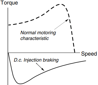
A typical torque–speed curve for braking a cage motor is shown in Figure 3, from which we see that the braking (negative) torque falls to zero as the rotor comes to rest. This is in line with what we would expect, since there will be induced currents in the rotor (and hence torque) only when the rotor is ‘cutting’ the flux. As with plugging, injection (or dynamic) braking is a dissipative process, all the kinetic energy being turned into heat inside the motor.