Influence of Rotor Parameters on Torque Speed Curves
We know that the rotor resistance and reactance influence the shape of the torque–speed curve. The designer can vary both of these parameters, and we will explore the pros and cons of the various alternatives. To limit the mathematics the discussion will be mainly qualitative, but it is worth mentioning that the whole matter can be dealt rigorously using the equivalent circuit approach.
We will deal with the cage rotor first because it is the most important, but the wound rotor allows a wider variation of resistance to be obtained, so it is discussed later.
Cage Rotor
For small values of slip, i.e. in the normal running region, the lower we make the rotor resistance the steeper the slope of the torque–speed curve becomes, as shown in Figure 1. We can see that at the rated torque (shown by the horizontal dotted line in Figure 1) the full-load slip of the low-resistance cage is much lower than that of the high-resistance cage.
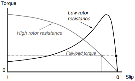
But we know that the rotor efficiency is equal to (1 – s), where s is the slip. So, we conclude that the low-resistance rotor not only gives better speed holding, but is also much more efficient. There is of course a limit to how low we can make the resistance: copper allows us to achieve a lower resistance than aluminium, but we can’t do anything better than fill the slots with solid copper bars.
As we might expect there are drawbacks with a low-resistance rotor. The starting torque is reduced (see Figure 1), and worse still the starting current is increased. The lower starting torque may prove insufficient to accelerate the load, while increased starting current may lead to unacceptable volt drops in the supply.
Altering the rotor resistance has little or no effect on the value of the peak (pullout) torque, but the slip at which the peak torque occurs is directly proportional to the rotor resistance. By opting for a high enough resistance (by making the cage from bronze, brass or other relatively high resistivity material) we can if we wish to arrange for the peak torque to occur at or close to starting, as shown in Figure 1. The difficulty in doing this is that the full-load efficiency is inevitably low because the full-load slip will be high (see Figure 1).
There are some applications for which high-resistance motors are well suited, an example being for metal punching presses, where the motor accelerates a flywheel, which is used to store energy. To release a significant amount of energy, the flywheel slows down appreciably during impact, and the motor then has to accelerate it back up to full speed. The motor needs a high torque over a comparatively wide speed range, and does most of its work during acceleration.
Once up to speed the motor is effectively running light, so its low efficiency is of little consequence. High-resistance motors are also used for speed control of fan-type loads.
To sum up, a high-rotor resistance is desirable when starting and at low speeds, while a low resistance is preferred under normal running conditions. To get the best of both worlds, we need to be able to alter the resistance from a high value at starting to a lower value at full speed.
Obviously we cannot change the actual resistance of the cage once it has been manufactured, but it is possible to achieve the desired effect with either a ‘double cage’ or a ‘deep bar’ rotor. Manufacturers normally offer a range of designs, which reflect these trade-offs, and the user then selects the one which best meets his particular requirements.
Double Cage Rotors
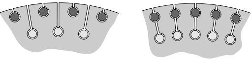
Double cage rotors have an outer cage made up of relatively high resistivity material such as bronze, and an inner cage of low resistivity, usually copper, as shown in Figure 2. The inner cage is sunk deep into the rotor, so that it is almost completely surrounded by iron.
This causes the inner bars to have a much higher leakage inductance than if they were near the rotor surface, so that under starting conditions (when the induced rotor frequency is high) their inductive reactance is very high and little current flows in them.
In contrast, the bars of the outer cage are placed so that their leakage fluxes face a much higher reluctance path, leading to a low-leakage inductance. Hence, under starting conditions, rotor current is concentrated in the outer cage, which, because of its high resistance, produces a high starting torque.
At the normal running speed the roles are reversed. The rotor frequency is low, so both cages have low reactance and most of the current therefore flows in the low-resistance inner cage. The torque–speed curve is therefore steep, and the efficiency is high.
Considerable variation in detailed design is possible to shape the torque–speed curve to particular requirements. In comparison with a single-cage rotor, the double cage gives much higher starting torque, substantially less starting current, and marginally worse running performance.
Deep Bar Rotors
The deep bar rotor has a single cage, usually of copper, formed in slots which are deeper and narrower than in a conventional single-cage design. Construction is simpler and therefore cheaper than in a double cage rotor, as shown in Figure 3.

The deep bar approach ingeniously exploits the fact that the effective resistance of a conductor is higher under a.c. conditions than under d.c. conditions. With a typical copper bar of the size used in an induction motor rotor, the difference in effective resistance between d.c. and say 50 or 60 Hz (the so-called ‘skin-effect’) would be negligible if the conductor was entirely surrounded by air. But when it is almost completely surrounded by iron, as in the rotor slots, its effective resistance at mains frequency may be two or three times its d.c. value.
Under starting conditions, when the rotor frequency is equal to the supply frequency, the skin effect is very pronounced, and the rotor current is concentrated towards the top of the slots. The effective resistance is therefore increased, resulting in a high-starting torque from a low-starting current.
When the speed rises and the rotor frequency falls, the effective resistance reduces towards its d.c. value, and the current distributes itself more uniformly across the cross section of the bars.
The normal running performance thus approaches that of a low-resistance single-cage rotor, giving a high efficiency and stiff torque– speed curve. The pullout torque is, however, somewhat lower than for an equivalent single-cage motor because of the rather higher leakage reactance.
Most small and medium motors are designed to exploit the deep bar effect to some extent, reflecting the view that for most applications the slightly inferior running performance is more than outweighed by the much better starting behaviour.
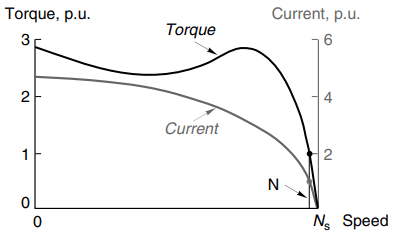
A typical torque–speed curve for a general-purpose medium-size (55 kW) motor is shown in Figure 4. Such motors are unlikely to be described by the maker specifically as ‘deep-bar’ but they nevertheless incorporate a measure of the skin effect and consequently achieve the ‘good’ torque–speed characteristic shown by the solid line in Figure 4.
The current–speed relationship is shown by the dotted line in Figure 4, both torque and current scales being expressed in per unit (p.u.). This notation is widely used as a shorthand, with 1 p.u. (or 100%) representing rated value.
For example, a torque of 1.5 p.u. simply means one and a half times rated value, while a current of 400% means a current of four times rated value.
Starting and Run-Up of Slipring Motors
By adding external resistance in series with the rotor windings the starting current can be kept low but at the same time the starting torque is high. This is the major advantage of the wound-rotor or slipring motor, and makes it well suited for loads with heavy starting duties such as stone-crushers, cranes and conveyor drives. The influence of rotor resistance is shown by the set of torque–speed curves in Figure 5.
The curve on the right corresponds to no added rotor resistance, with the other six curves showing the influence of progressively increasing the external resistance.
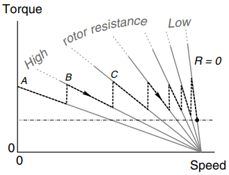
A high-rotor resistance is used when the motor is first switched on, and depending on the value chosen any torque up to the pullout value (perhaps twice full load) can be obtained. Typically, the resistance will be selected to give full-load torque at starting, together with rated current from the mains. The starting torque is then as indicated by point A in Figure 5.
As the speed rises, the torque would fall more or less linearly if the resistance remained constant, so to keep close to full-load torque the resistance is gradually reduced, either in steps, in which case the trajectory ABC etc. is followed (see Figure 5), or continuously so that maximum torque is obtained throughout.
Ultimately the external resistance is made zero by shorting-out the sliprings, and thereafter the motor behaves like a low-resistance cage motor, with a high running efficiency. As mentioned earlier, the total energy dissipated in the rotor circuit during run-up is equal to the final stored kinetic energy of the motor and load. In a cage motor this energy ends up in the rotor, and can cause overheating.
In the slipring motor, however, most of the energy goes into the external resistance. This is a good thing from the motor point of view, but means that the external resistance has to absorb the thermal energy without overheating. Fan-cooled grid resistors are often used, with tappings at various resistance values. These are progressively shorted-out during run-up, either by a manual or motor-driven drum-type controller, or with a series of timed contactors.
Alternatively, where stepless variation of resistance is required, a liquid resistance controller is often employed. It consists of a tank of electrolyte (typically caustic soda) into which three electrodes can be raised or lowered. The resistance between the electrodes depends on how far they are immersed in the liquid.
The electrolyte acts as an excellent short-term reservoir for the heat released, and by arranging for convection to take place via a cooling radiator, the equipment can also be used continuously for speed control.
Attempts have been made to vary the effective rotor circuit resistance by means of a fixed external resistance and a set of series connected thyristors, but this approach has not gained wide acceptance.
Influence of Supply Voltage on Torque Speed Curve
At any given slip, the air-gap flux density is proportional to the applied voltage, and the induced current in the rotor is proportional to the flux density. The torque, which depends on the product of the flux and the rotor current, therefore depends on the square of the applied voltage.
This means that a comparatively modest fall in the voltage will result in a much larger reduction in torque capability, with adverse effects which may not be apparent to the unwary until too late. To illustrate the problem, consider the torque–speed curves for a cage motor shown in Figure 6.
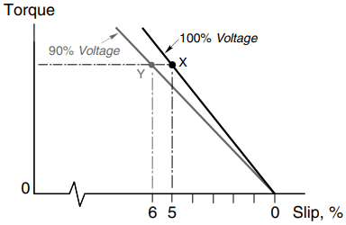
The curves (which have been expanded to focus attention on the low-slip region) are drawn for full voltage (100%), and for a modestly reduced voltage of 90%. With full voltage and full-load torque the motor will run at point X, with a slip of say 5%. Since this is the normal full-load condition, the rotor and stator currents will be at their rated values.
Now suppose that the voltage falls to 90%. The load torque is assumed to be constant so the new operating point will be at Y. Since the air-gap flux density is now only 0.9 of its rated value, the rotor current will have to be about 1.1 times rated value to develop the same torque, so the rotor e.m.f. is required to increase by 10%.
But the flux density has fallen by 10%, so an increase in slip of 20% is called for. The new slip is therefore 6%. The drop in speed from 95% of synchronous to 94% may well not be noticed, and the motor will apparently continue to operate quite happily. But the rotor current is now 10% above its rated value, so the rotor heating will be 21% more than is allowable for continuous running.
The stator current will also be above rated value, so if the motor is allowed to run continuously, it will overheat. This is one reason why all large motors are fitted with protection, which is triggered by over-temperature. Many small and medium motors do not have such protection, so it is important to guard against the possibility of under-voltage operation.