Frequency Counter
The most basic function of a frequency counter is the measurement of an unknown frequency. Modern frequency counters, however, offer much more than just frequency measurement. Other related parameters such as the time period, which is the reciprocal of frequency, the time interval between two events and the totalize count, which is nothing but the cumulative count over a known period, are other functions that are available with present-day frequency counters. These instruments, offering a variety of measurement options, are usually referred to as universal counters.
Universal Counters – Functional Modes
The functions available with modern universal counters, other than measurement of an unknown frequency, are time interval measurement, period, time interval average, totalize, frequency ratio A/B, phase A relative to B and pulse width.
Time Interval Measurement: This mode measures the time that elapses between the occurrence of two events. One of the events, called the start signal, is usually fed into one of the channels, while the other, called the stop signal, feeds the second channel. The resolution of measurement is typically 10 ns or better.
A typical application of this measurement mode is in determination of the propagation delay in logic circuits. Variations of this mode can be used to measure pulse width and rise/fall times.
Time Interval Average: This mode can be used to improve the measurement resolution in the time interval measurement mode for a given clock frequency. The resolution improves as the square root of the number of measurements. That is, an average of 100 measurements would give a 10 fold improvement in resolution.
Period: In this mode, the time period of the input signal is measured by counting clock pulses between two successive leading or trailing edges of the input signal. Again, the period average function can be used to improve upon the measurement resolution for a given clock.
For instance, if the measurement were done for 100 periods instead of one period for a given clock frequency, the measurement resolution would also improve by a factor of 100.
Totalize: The totalize mode gives a cumulative count of events over a known time period.
Frequency Ratio A/B: This gives the ratio of the frequencies of signals fed to the A and B channels. This feature can be used to test the performance of prescalers and frequency multipliers.
Phase A Relative to B: This compares the phase delay between signals with similar frequencies.
Basic Counter Architecture
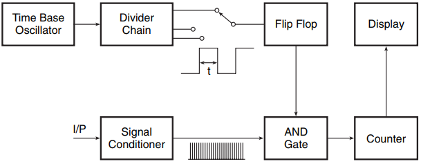
Figure 1 shows the architecture of a frequency counter when it is being used in the frequency measurement mode. The oscillator section, comprising a crystal-based oscillator and a frequency divider chain, generates the clock pulses. The clock pulses are used to trigger a flip-flop whose output serves to enable or disable the AND gate.

When the AND gate is enabled, the input signal, after passing through the signal conditioning section comprising level shifting amplifiers, comparators, etc., reaches the counter. In the simplest case, if the AND gate is enabled for 1 s (which is the case when the flip-flop clock input is 1 Hz), then the counter count will represent the signal frequency.
The measurement resolution in this case would be 1 Hz. The measurement resolution can be improved by enabling the AND gate for a longer time. For instance, a 0.1 Hz clock at the flip-flop input would give a 10 s gate time and a consequent 0.1 Hz resolution. Similarly, a shorter measurement for a gate time of 0.1 s (corresponding to a clock of 10 Hz) gives a measurement resolution of 10 Hz.

The same building blocks, when slightly rearranged as shown in Fig. 2, can be used to measure the time period. Enabling and disabling of the AND gate are now determined by the frequency of the input signal and not by the clock frequency. The number stored in the counter here is proportional to the number of clock pulses that reach the counter during the period of the input signal.
The same set-up can be used for time interval (TI) measurement by having two input signal channels, with one enabling the AND gate by, say, setting the flip-flop and the other disabling the same by resetting the flip-flop.
Reciprocal Counters
The reciprocal counter overcomes some of the limitations of the basic counter architecture described in the previous paragraphs. Most important of all is its inadequate resolution, particularly when measuring low frequencies. The basic counter had a resolution of 1 Hz for a gate time of 1 s and the resolution could be enhanced only by increasing the gate time.
If the gate time cannot be increased in a certain application, the resolution is restricted to 1 Hz. The basic counter measures frequency in terms of event count. Depending upon the gate time, which is 1 s or any other decade value such as 10, 100, etc., the decimal point appropriately placed in the count gives frequency.
What is important to note here is that computation of frequency involves computation of the event count only. The frequency, which is given by the event count divided by the time taken, is calculable from the event count itself if the time is 1 s, 10 s, 100 s, etc. In a reciprocal counter, both events as well as time are computed and the ratio of the two gives the frequency.
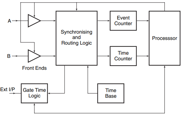
The advent of the reciprocal counter was made possible owing to the availability of digital logic that could perform arithmetic division economically and with precision. Figure 3 shows the reciprocal counter hardware. The processor is the heart of the counter hardware and controls almost every other building block.

The synchronizing and routing logic block routes the A and B channel inputs and the time-base signal to the event and time counters. The routing is determined by the measurement function. The computations are done in the processor block.
As a matter of comparison, let us see how the two counters having an internal clock of 10 MHz would respond to measurement of a signal frequency of 50.38752 Hz. The basic counter will display 50 Hz, assuming a gate time of 1 s as the event count will be 50. The reciprocal counter will also have an event count of 50 but it will also measure time with a resolution of 100 ns (for a 10 MHz clock), equal to 0.9923328 s.
The measured frequency will therefore be 50.38752 Hz. The frequency resolution offered for a 10 MHz clock is seven digits, equal to 0.000005 Hz in the present case for a 1 s gate. The resolution could be further enhanced by increasing the clock frequency. Since clock frequencies of up to 500 MHz are practical, a reciprocal counter would give a resolution of 2 ns for a 1 s gate time.
The resolution of reciprocal counters can be further enhanced by using a technique called interpolation. It is possible to achieve a nine-digit resolution with a 10 MHz clock using interpolation techniques that otherwise would require a clock of 1 GHz.
This is particularly important when we are looking for a given resolution in shorter gate times. The details of interpolation techniques are beyond the scope of this text.
Continuous-Count Counters
The counter architectures discussed in the previous paragraphs had a counter that counted for a known period equal to the gate time. These counters have a dead time when the gate is disabled. Such counters could miss vital information that could be important to the measurement.
The continuous-count counter architecture is based on the fact that, if different measurements of a certain parameter of a signal were not disjoint and the relationship that they had were made use of, the measurement resolution could be significantly enhanced by applying what we call curve-fitting algorithms.
These counters have all the attributes of reciprocal counters, with the additional ability of reading the event, the time and the counter without having to disable the gates.
Frequency Counter Specifications
The data sheets and manuals of universal counters contain detailed specifications of the instrument. The important ones include sensitivity, bandwidth, resolution, accuracy and throughput.
Sensitivity: This refers to the smallest signal that the instrument can measure and is usually expressed as mV (RMS) or peak-to-peak. A sensitivity of 10–20 mV (rms) is typical. In the majority of measurement situations, sensitivity is not the issue.
Bandwidth: The bandwidth of the counter is its front-end bandwidth and is not necessarily the same as the maximum frequency that the counter is capable of measuring. Measuring a signal frequency higher than the instrument’s bandwidth only reduces its sensitivity specification and requires a larger minimum input signal.
However, the bandwidth does affect the measurement accuracy in the case of some parameters. Rise time is one such parameter. Thus, it is always preferable to choose a counter with as high a bandwidth as possible. Bandwidth is not explicitly mentioned in the specifications. However, it can be estimated by looking at variation in sensitivity across the frequency range of the instrument.
Resolution: Resolution refers to the minimum resolvable frequency increment (in the case of frequency measurement) and time increment (in the case of time interval measurement). The resolution is usually very close to the least significant digit and is often ±1 count or LSD. Noise in the input signal, noise in the front end and input signal slew rate are some of the factors that affect resolution.
Accuracy: Accuracy is related to resolution but is not the same as resolution. Factors such as time-base (or clock) accuracy and trigger accuracy must be considered along with the resolution specification to determine the ultimate accuracy of frequency measurement. Time-base error affects measurement accuracy as follows:
Frequency accuracy = resolution ± time base error × frequency
Trigger level accuracy is the precision with which the trigger level can be set. If there is an error in the trigger level setting, the trigger timing is changed, thus affecting measurement accuracy.
Throughput: Throughput is related to resolution. For instance, increasing the gate time of a certain frequency measurement increases the measurement resolution by the same factor, but it slows down the throughput by almost the same amount. Other factors affecting the throughput are more related to the speed of the microprocessor and the interface system.
Two factors to be watched here are the number of measurements the counter can deliver through the interface and the speed with which the counter can switch between different functions or set-ups. If short gate times are being used and/or measurements are being switched between different functions repeatedly, these factors become important.
Microwave Counters
The counter architectures discussed in the preceding paragraphs (conventional, reciprocal, continuous count) are usually good enough up to 500 MHz or so. Counters meant for carrying out measurements at RF frequencies beyond 500 MHz and microwave frequencies employ a different architecture. There are two types of architecture in use for building microwave counters. One uses a prescaler while the other is based on down-conversion.
Prescaler counters use a prescaler placed between the front end and the gating circuitry of the counter. In fact, prescalers are available inside the counters as an optional channel to extend the frequency range of measurement. Extension up to 3 GHz is typically available with a prescaler.
Prescalers are not used with pulsed microwave counters owing to their tendency to self-oscillation. When used with a basic counter, a prescaler causes degradation of resolution. This is because the frequency resolution of a basic counter is dependent upon the contents of the event counter and, owing to the location of the prescaler before the gating circuitry, its contents cannot be read.
The resolution is not affected when the same is used in a reciprocal counter.
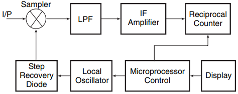
In a microwave counter based on down-conversion architecture, the input signal frequency is down-converted to produce an intermediate frequency (IF). The IF, which is the difference between the input signal frequency and the local oscillator (LO) frequency, is then counted. The actual frequency is then computed from LO + IF. Covering a frequency range of tens of GHz for an LO is an expensive proposition. The solution is to use a relatively lower-frequency LO (approximately 200 MHz).
The LO drives a step recovery diode that produces a sharp pulse with usable harmonics up to the desired range. This pulse drives a sampler which samples points of the input signal. The resulting IF is low-pass filtered and counted.
The actual input frequency is then given by N ×LO + IF, where N is the harmonic of the LO that goes through the mixing operation. One of the methods for determining N is to measure the IF at two slightly different LO frequencies. N is then given by (IF1–IF2) / (LO2–LO1). However, all this is the instrument’s headache and may take several tens of milliseconds only.

Figure 4 shows the architecture of a microwave counter. Pulse microwave counters use similar architecture with additional gating circuitry to position the gate comfortably within the pulse.
Related Posts
- Logic Gates
- Significance & Types of Logic Family
- Characteristics Parameters of Logic Families
- TTL Logic Family
- ECL Logic Family
- CMOS Logic Family
- Interfacing of Logic Families
- Microcontroller Architecture
- Components of Microcontroller
- Interfacing Devices with Microcontroller
- IC Based Multivibrator Circuits
- Astable, Monostable & Bistable Multivibrator
- Logic Analyser
- Types of Oscilloscope
- Frequency Synthesizers
- Frequency Counter