Frequency Synthesizers
Frequency synthesizers generate sinusoidal signals of extremely high frequency stability and exceptional output level accuracy. Frequency synthesizers and similar instruments such as synthesized function/signal generators are used to provide test signals for characterization of devices, subsystems and systems.
Synthesized function generators, in addition to providing spectrally pure and accurate CW sinusoidal signals, also provide other waveforms such as ramp, triangle, square and pulse. Synthesized signal generators, in addition to providing spectrally pure and accurate CW signals, also have modulation capability and can be used to generate AM, FM, PM and pulse-modulated signals.
There is another class of synthesized function generators called synthesized arbitrary waveform generators.
The majority of synthesized function generators have a limited arbitrary waveform generation capability built into them. However, these are available as individual instruments also.
All the above-mentioned instruments have one thing in common, that is, the synthesis of a signal that lends ultrahigh frequency stability and amplitude accuracy to the generated waveform. They therefore have more or less similar architecture for a given technique used for frequency synthesis.
Direct Frequency Synthesis
The frequency synthesizer in its basic form uses a reference oscillator, which is an ultrastable crystal oscillator, and other signal-processing circuits to multiply the oscillator frequency by a fraction M/N (where M and N are integers) in order to generate the desired output frequency. One such arrangement is shown in Fig. 1.
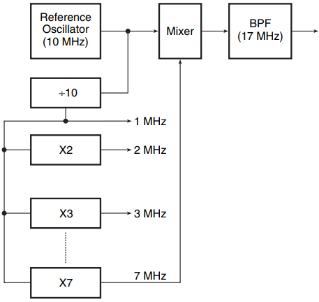
It comprises an assortment of frequency multipliers and dividers, mixers and band-pass filters (BPFs). The diagram shows the use of this architecture to generate 17 MHz. In this arrangement, if the BPF has a pass band centred around 3 MHz, the output will be 3 MHz as the mixer produces both sum and difference components.
This method of frequency synthesis has several disadvantages, not least that the technique is highly hardware intensive and therefore expensive. Another disadvantage is loss of phase continuity while switching frequencies, with the result that this technique has not found favour with designers.
Indirect Frequency Synthesis
In indirect synthesis, the output is not directly derived from the quartz crystal based reference oscillator. Instead, the reference oscillator is used in a phase-locked loop wired as a frequency multiplier to generate an output frequency that is M/N times the reference oscillator frequency. The output is taken from the VCO of the phase-locked loop.
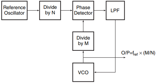
Figure 2 shows the basic arrangement. If we insert a divide-by-N circuit between the reference oscillator and the phase detector signal input and a divide by-M circuit between the VCO output and the phase detector VCO input, then the loop will lock with the VCO output as fref× (M/N). The frequency resolution of this architecture is fref /N, where fref is the frequency of the reference oscillator.
The loop frequency switching speed is of the order of 10 times the period of reference frequency input to the loop phase detector. That is, if we desired a frequency resolution of 1 Hz, the switching time would be of the order of 10 s, which is highly unacceptable.
Another disadvantage of this architecture is that frequency multiplier loops also multiply noise at the phase detector, which manifests itself in the form of noise sidebands at the VCO output. This restricts the maximum multiplication factor to a few thousands in this arrangement, which limits the resolution.
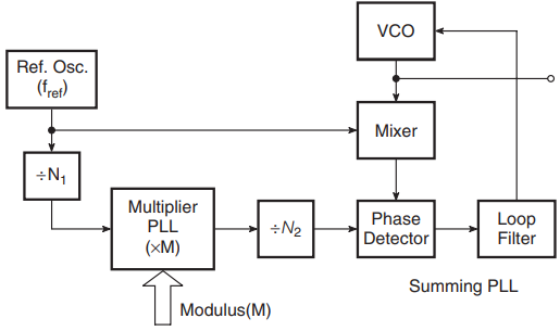
If a finer resolution is needed, sequences of multiplication, division and addition are used that involve more than one phase-locked loop. One such arrangement is shown in Fig. 3. The synthesizer output in this case is given by
fref× [m/(N1 × N2 + 1].
This technique can be extended to get any desired resolution. Since the multiplication numbers are low and the loop frequency is high, the output will have low noise sidebands. Also, the synthesizer is capable of fast frequency switching.
Another popular method of indirect synthesis is fractional N synthesis, where a single PLL is made to lock to the non-integer multiple of the loop reference. This technique can be used to achieve a frequency resolution of micro-hertz order at switching speeds of the order of a millisecond or so. Figure 4 shows the basic architecture. The configuration functions as follows.
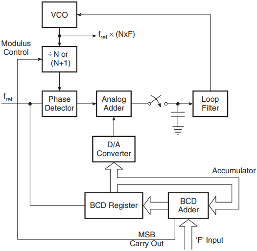
The integer part of the desired multiplier is supplied to the digital divider placed between the VCO output and the phase detector in the form of its dividing factor. The fractional part is supplied to the accumulator. The accumulator is clocked by the reference source derived from the crystal oscillator.
The quantum of fractional input is added to the accumulator contents every clock cycle. The VCO output is N × F times the reference input when the loop is locked.
The circuit functions in such a way that the contents of the accumulator predict the expected phase detector output resulting from the frequency difference of the two phase detector input signals. The D/A converter is then so scaled and polarized that its output waveform cancels the phase detector output waveform.
The two waveforms are added in the analogue adder, sampled and filtered to provide the oscillator control voltage. Also, to keep the phase detector output within its linear range, whenever the phase difference between the two inputs to the phase detector tends to become 360o which is the maximum the phase detector can tolerate without going out of range, the phase of the divider output (which is ahead of the reference input in phase) is retarded by 360 by either changing the divider modulus to N +1 momentarily or by any other means.
In the architecture shown, the modulus is changed to accomplish this on receiving a command from the BCD adder at the time of accumulator overflow.
Sampled Sine Synthesis (Direct Digital Synthesis)
This method of frequency synthesis is based on generating the waveform of desired frequency by first producing the samples as they would look if the desired waveform were sampled or digitized according to the Nyquist sampling theorem, and then interpolating among these samples to construct the waveform.
As the frequency is the rate of change in phase, this information is made use of to generate samples. The sine of different phase values is stored in a memory, which is addressed by phase increment information stored in an accumulator. Figure 5 shows a simplified block schematic representation of direct digital synthesis.
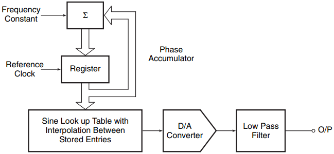
When the accumulator is clocked at a fixed frequency, the contents of the accumulator jump by the phase increment whose digital equivalent information is stored in the phase increment register (PIR). By changing the contents of the PIR, the output frequency can be changed. The rate at which the look-up table in the memory is addressed is given by the clock frequency and phase increment during one clock period as given by the PIR contents.
For instance, if the contents of the PIR represented a phase angle of 36, then the digital samples present at the output of the memory would correspond to phase differences of 36, 72, 108, 144, 180, 216, 252, 288, 324 and 360 to complete one cycle of output waveform.
The 10 samples will be produced in 10 clock cycles. Therefore, the output frequency will be one-tenth of the clock frequency. In general, the output frequency is given by ϕ/2 × fclock where ϕ is the phase increment in radians.
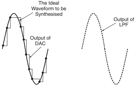
The digital samples are converted into their analogue counterparts in a D/A converter and then interpolated to construct the waveform. The interpolator here is a low-pass filter. Relevant waveforms are shown in Fig. 6.
This method of synthesis derives its accuracy from the fact that both the phase increment information and the time in which the phase increment occurs can be computed to a very high degree of accuracy. With the frequency being equal to the rate of change in phase, the resulting waveform is highly stable.
The most important feature of this technique, however, is its capability to provide instantaneous switching. This is possible because the size of the angle increments between two consecutive table look-ups may be changed instantaneously.
The limitations of this technique are the quantization noise and aliasing inherent in any sampled data system. Another serious disadvantage is the presence of spurious components owing to imperfections and inaccuracies in the D/A converter. The highest frequency that can be synthesized is limited by the maximum speed of the available digital logic. The usable frequency range of the direct digital synthesis output may be extended by a variety of techniques.
However, depending upon the technique used, some of the advantages of this technique may be lost. As in the case of more conventional synthesizers, the output of a direct digital synthesizer may be doubled, mixed with other fixed sources or used as a reference inside a PLL.
Specifications of Frequency Synthesizer
Frequency range, resolution, frequency switching speed and signal purity are the important synthesizer specifications.
Frequency Range and Resolution: While considering the frequency range, it is important to note whether the claimed frequency range is being covered in a single band or a series of contiguous bands. This aspect is significant from the viewpoint of noise performance, which may be different in different bands in cases where the frequency range is covered in more than one band.
This often leads to a larger transient when the frequency switching involves switchover of the band also. Frequency resolution is usually the same throughout the range. It is typically 0.1 Hz, although a resolution as fine as 1 mHz is also available in some specific instruments.
Frequency Switching Speed: The frequency switching speed is a measure of the time required by the source to stabilize at a new frequency after a change is initiated. In the PLL-based synthesizers it depends upon the transient response characteristics of the loop. The switching time is typically several hundreds of microseconds to tens of milliseconds in PLL-based synthesizers and a few microseconds in instruments using the direct digital synthesis technique.
Signal Purity: The signal purity tells how well the output signal approximates the ideal single spectral line. Phase noise is one parameter that affects signal purity. This refers to the sidebands that result from phase modulation of the carrier by noise. It is specified as the total sideband power (in decibels) with respect to the carrier.
The presence of spurious signals resulting from undesired coupling between different circuits within the instrument and distortion products in the signal mixers also spoils signal purity.
Synthesized Function Generators
Synthesized function generators are function generators with the frequency precision of a frequency synthesizer. The hardware of a synthesized function generator is similar to that of a frequency synthesizer with additional circuitry to produce pulse, ramp, triangle and square functions. These instruments with additional modulation capability are referred to as synthesized signal generators.
Direct digital synthesis described in this article is almost invariably used in synthesized function/signal generator design. Advances in digital technology have made these synthesized function/signal generators truly versatile. Synthesized sine wave output up to 30 MHz and other functions such as pulse, ramp, triangle, etc., up to 100 kHz, all with a resolution of 1µHz, are available in contemporary synthesized function generators.
Arbitrary Waveform Generator
The arbitrary waveform generator (AWG) is a signal source that is used to generate user-specified custom analogue waveforms. Using a custom stimulus waveform and measuring the response waveform provides realistic characterization of the device or system under test. The contemporary AWG allows generation of almost any conceivable waveform. Direct digital synthesis again is the heart of an arbitrary waveform generator.
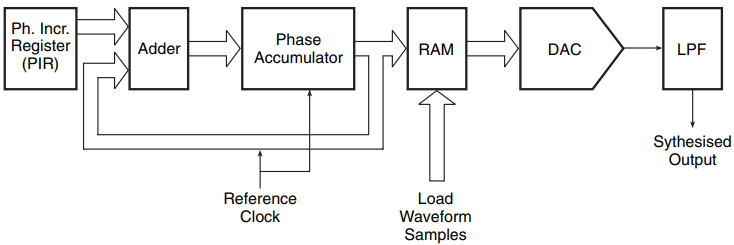
Figure 7 shows the hardware. It looks very similar to the one shown in Fig. 5. The sequential amplitude values of the waveform to be generated are stored in the RAM. The size of the RAM decides the number of samples that can be stored, which in turn decides the maximum number of samples into which one period of the desired waveform can be divided. These sample values can be entered into the RAM from the keyboard.
Once the sample values are loaded into the RAM, they can be stepped through at a repetition rate governed by the frequency word input to the phase accumulator in the same way as explained in the case of a frequency synthesizer. The complexity of the waveform that can be synthesized by this process is limited by the size of the RAM.
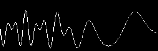
As a rule of thumb, a minimum of about 3–4 samples per cycle of the highest frequency in the waveform should be used. This is intended to eliminate aliasing. Figure 8 shows a typical arbitrary waveform possible in a typical arbitrary waveform generator.
Related Posts
- Logic Gates
- Significance & Types of Logic Family
- Characteristics Parameters of Logic Families
- TTL Logic Family
- ECL Logic Family
- CMOS Logic Family
- Interfacing of Logic Families
- Microcontroller Architecture
- Components of Microcontroller
- Interfacing Devices with Microcontroller
- IC Based Multivibrator Circuits
- Astable, Monostable & Bistable Multivibrator
- Logic Analyser
- Types of Oscilloscope
- Frequency Synthesizers
- Frequency Counter