PV Arry Charge Controllers
Charge controllers are used to control the current coming from a power source. The charge controllers that are commercially available come in a variety of sizes and have an assortment of features.
Small charge controllers can be used in very small systems with one or two PV modules charging a small battery bank. Larger charge controllers are designed for use with multiple-kilowatt arrays and large battery banks.
In this article, I tell you all about the main functions, special features, and types of charge controllers. I also explain how to specify (select) a
controller for the particular system you’re designing.
The Essentials of Charge Controllers
Simply stated, in order to properly maintain a battery bank that’s being recharged by a PV array, you must include a charge controller in the system design. In the sections that follow, I introduce the basic functions of a charge controller and describe the features offered on some models.
How a Charge Controller Works
A charge controller’s main role in a PV system is to properly control the charge from the PV array into the battery bank by controlling the current and voltage from the array into the batteries.
Without a charge controller, the PV array would be able to send all of its current into the battery bank without any regard for the batteries’ needs. The batteries, in turn, would become overcharged and eventually ruined.
Each charge controller has multiple stages for which it regulates different voltage and current levels; in Figure 1, you can see three such stages.
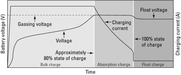
This figure shows how both the voltage and current vary over time based on the charge set-points, which are the voltage levels that you want to charge the batteries to; each battery manufacturer publishes its own charge set-points that you should use if you want to maximize the batteries’ life span. (Note: During the installation process and before commissioning the system, you must adjust the charge set-points as necessary.)
In the following sections, I describe a charge controller’s role during the three charging stages.
Bulk charging: The first charging stage is bulk charging. It happens first thing in the morning after the batteries’ voltage and capacity have been drained down since the sun set the previous day. Bulk charging pushes as many amps as possible back into the battery bank from the PV array and gets the voltage up in the process.
To better understand bulk charging, it may help to equate it with trying to fill a large glass of water from your faucet. The voltage is the water level in the glass. If the voltage in the battery (or the water level in the glass) is relatively low, then you need to allow as much current from the PV array as possible into the battery (in other words, you need to open that faucet all the way).
In this analogy, the charge controller is the faucet that controls how much water (current) can flow into the glass. Both the PV array and the faucet are limited in the flow they can provide to their respective containers, but as long as the level of energy (or water) in the container is low, the container (the battery or the glass) will gladly and readily accept the flow. As the current (or water) continues to flow, the battery voltage (the water level in the glass) continues to rise. This charging process continues until the battery voltage reaches a predetermined level known as the bulk voltage set-point.
At this point, the current needs to slow down. If it doesn’t, the battery can’t effectively accept the charge, and the current becomes heat (or, in the case of the water glass, the water simply starts spilling over the edge).
The exact bulk voltage set-point is determined by the battery manufacturer. Some batteries are able to take a higher charging voltage than others, so you need to make sure your controller is set correctly for the batteries you’re using, as indicated in the owner’s manuals provided by the controller and battery manufacturers.
The voltage is taken above this set-point on purpose during the equalization charge; this is a deliberate act that requires monitoring and should only be done according to the manufacturer’s recommendations.
If the batteries are consistently charged above the bulk voltage set-point, the overall life of the battery bank will be greatly reduced.
Absorption charging: The second charging stage in the three-stage charging process is absorption charging. After a battery bank has been brought up to the bulk voltage set-point (see the preceding section for more on this), it can’t really accept high levels of current. If it’s forced to, the end result will be heat generation and excessive gas production — not a good thing.
When a battery reaches its manufacturer’s bulk voltage set-point, it’s really only about 80-percent full. The point of the absorption charge is to top off the battery.
Think about a glass of water under a faucet. If you stop the flow just before the water spills over the edge, when you turn the faucet off, the glass isn’t 100-percent full because the force of the water was pushing it over the top.
During the absorption-charging stage, the charge controller holds the battery voltage constant and reduces the amount of current sent into the battery bank. (It’s like reducing the flow from the faucet to top off the water level in the glass.) When this process is done, the bank is fully recharged.
Typically, a full battery-charging cycle (bulk and absorption) is a multiple- hour event; the exact length of time required depends on the size of the battery bank and the PV array.
The charge controller automatically starts and stops the charging stages, but if the charging source is the PV array, there’s always the chance that the sun will disappear before the controller has the opportunity to finish its work.
In this scenario, the battery bank doesn’t reach 100-percent capacity and needs an additional charging source, such as the utility grid or an engine generator, to help it get there.
Float charging: The final charging stage is float charging, and it’s designed to keep the battery in a full state of charge after the absorption-charging stage has topped off the battery bank.
Typically, a PV array spends only a small amount of time float-charging the battery bank due to the limited number of hours it has each day to recharge the bank.
A charge controller enters into a float-charging stage only after the first two charging stages have been completed and when there’s enough power from the array to send a float charge into the batteries.
When the number of peak sun hours is very limited (like during the winter), a PV array may not be able to get the battery bank to the float voltage at all because the lack of sun doesn’t allow for a full charging cycle and because the bank may be drained relatively low due to greater use.
In the summer, an array may be able to recharge the battery bank in a short amount of time, allowing it to spend a fair portion of the day in the float-charging stage.
Special Effects Provided by Some Charge Controllers
Some of the small charge controllers used in PV systems have only one feature: the ability to regulate the charge entering the battery from the PV array. Others, like those designed to work with larger systems (greater than 500 W), may include a variety of additional features to complement the main battery-charging feature.
The need for and use of these features, which I explain in the next sections, vary among PV systems, but all of these features are available in every type of charge controller.
Load control: In systems that support direct current (DC) loads (namely, stand-alone, battery-based systems, although DC loads can be supported anytime batteries are present), some charge controllers employ a load-control feature to make sure the batteries don’t become excessively discharged. This feature works by pulling electricity directly from the battery bank and sending it to the loads through the charge controller.
As the loads continue to run, the battery bank’s capacity is reduced and monitored by the charge controller. If the loads run long enough, the charge controller senses the batteries’ reduced capacity and cuts off the flow to the loads, which ensures the connected loads don’t drain the batteries too low and cause them harm.
The load-control feature doesn’t allow the loads to receive power again until the battery bank has been recharged to a certain point, eliminating the possibility of the loads being reconnected to the bank before sufficient capacity is restored in the batteries.
DC lighting loads are some of the most common devices used in con- junction with the load-control feature, although most any electrical appliance that can run off of DC electricity can be controlled.
Auxiliary load control: In certain situations, there may be a need (or desire) to run loads only when the battery bank is being charged excessively or when the battery bank is running low and needs attention.
These auxiliary loads (additional loads on top of what the building is using) are used to enhance the safety or performance of the entire PV system.
Fortunately, some charge controllers include relays that can close an electrical switch when the battery reaches a certain level and send power to an auxiliary load. One common auxiliary load is a fan connected to a flooded battery bank’s enclosure.
When the PV array (or other charging source) brings the battery voltage up to a certain charge level, the flooded batteries begin to release hydrogen gas. The auxiliary-load-control feature of a charge controller is activated when the batteries reach the predetermined voltage and power is sent to the fan (which in this case is the auxiliary load).
Other auxiliary loads such as warning lights or alarms can be connected to warn your client about a battery’s excessive or reduced voltage levels.
Status meters: Some charge controllers feature status meters that can either be integrated into the face of the controller or be run remotely for a client to see in a convenient location (such as the kitchen or other living space).
Status meters allow PV system owners to evaluate the battery and PV array voltage levels of their system with a quick glance. Other, more sophisticated status meters also track the energy values into and out of the battery bank.
These amp-hour meters are especially useful to owners of stand-alone, battery-based systems who rely on their battery banks for the majority of their power. By using a status meter that includes an amp-hour meter, your client can accurately know the status of her battery bank and know when she needs a secondary charging source, such as an engine generator, to bring the battery capacity back up.
This level of monitoring is actually quite important for stand-alone systems because the batteries are the user’s main power source; as such, she should know their status at all times.