Maximum Power Point Tracking Technology
The technology that allows a PV array to deliver the maximum amount of energy to a battery bank is known as maximum power point tracking (MPPT). MPPT charge controllers gained popularity in the early 2000s when manufacturers released highly reliable and accurate versions that allowed users to maximize the charging ability of their PV array and, in some cases, reduce the required PV array size for battery charging compared to some of the older technology.
In the following sections, I explain the magic behind MPPT controllers and outline their pros and cons so you can evaluate whether this technology is the right solution for your clients.
Note: All commercially available grid-direct inverters also use MPPT technology.
How MPPT Works
An MPPT charge controller uses the three charging stages presented earlier in this chapter to allow a PV array to operate at its maximum power point (abbreviated MPP) regardless of the voltage of the battery bank connected to the controller.
Other charge controller technologies, such as pulse-width modulation, can’t fully use a PV array’s MPP.
The MPP is defined as the point on the IV curve where the current multiplied by the voltage yields the highest power value. (In other words, it’s the product of the maximum power voltage, Vmp, and the maximum power current, or Imp.)
For a typical 12 V nominal panel, the voltage associated with the MPP is somewhere around 17 V. PV manufacturers realized early on that this was the voltage value required to effectively charge a 12 V nominal battery bank in nearly all worldwide geographic locations. (Keep in mind that module voltage decreases when the module temperature rises, so the extra voltage is necessary to push the electrons into the battery bank when the module’s temperature is elevated.)
The maximum power voltage of 17 V doesn’t always equate directly to the required voltage needed to charge a battery bank, though.
Depending on the technology and the charge set-point, the voltage necessary for charging a 12 V nominal battery bank can range anywhere from 13 V to 15 V. Therefore, a PV module can produce more voltage than a battery bank can fully use.
MPPT controllers take the power from a PV array at the MPP, regardless of the required battery voltage, and deliver that same amount of power (minus efficiency losses, of course) to the battery bank because they’re able to reduce the voltage from the array to the battery’s required level.
And because power is the product of voltage and current, if the voltage is decreased, the current is increased in order to keep the same power level. MPPT controllers boost current into the battery bank in relation to the current received from the array.
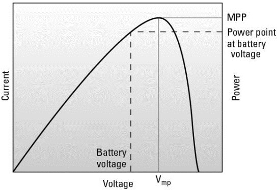
I think this concept is best illustrated in Figure 2, which depicts the power curve for a typical 12 V nominal PV module. The peak of the curve represents the maximum power value, which is the level that the PV module can produce. The graph also shows the location of a typical battery charge set-point.
If you move straight over to the right from that point, you’ll see the power level associated at the battery-charging voltage.
The difference in the MPP and the power level associated with the battery-charging voltage represents the increased power output due to the use of the MPPT technology. The PV array’s power levels move throughout the day depending on the environmental conditions, and MPPT controllers adjust right along with them.
Pros and Cons of MPPT Controllers
MPPT controllers have become the most popular charge controllers for larger battery-based PV systems (both stand-alone and utility-interactive) thanks to their ability to fully use the power produced by a PV array.
Another good thing MPPTs have going for them is their ability to take a PV array wired for a higher voltage and still charge a low-voltage battery bank.
For example, with the help of an MPPT controller, you can take a PV array that’s wired in a series configuration up to 150VDC and still charge a battery bank all the way down at 12 V nominal. Having a higher-voltage array allows your client to locate the PV array farther from the battery bank and not have to take out a second mortgage for the length of wire connecting the two.
Finally, MPPT manufacturers are constantly adding features and increasing efficiencies. These improvements help you, the designer and installer, by increasing the flexibility in your design.
A major drawback to MPPT controllers is the cost. This technology comes at a price (about $800 for a standard unit as of early 2010). Justifying the extra expense for very small systems that don’t fully realize all the benefits can be difficult, which is why MPPT controllers are often used only in larger arrays.
Pulse Width Modulation Technology
Although not as sleek and sophisticated as MPPT, pulse-width modulation (PWM) charge controllers are very effective in charging battery banks and will likely be a popular technology used in PV systems for years to come.
In the sections that follow, I describe the workings of PWM technology and note the pros and cons of using it so you can decide what’s best for your clients.
How PWM Works
Just like MPPT controllers, PWM controllers regulate battery charging via multiple set-points. However, unlike MPPT controllers, PWM controllers can only use the voltage from the array that equals the voltage required by the batteries. (For example, if the battery bank needs 14 V to charge and the array can supply 17 V, the controller can only accept the 14 V.)
This characteristic inherently reduces the overall power available from the PV array because the battery-charging voltage rarely matches the array’s maximum power voltage.
Because the battery bank dictates the voltage, the amount of current sent into the battery from the array is also limited (so the current value from the array that’s associated with the battery-charging voltage is different from the maximum power point current).
As the battery bank gets full, the PWM controller regulates the charge into it by pulsing the charge (turning the power on and off) from the array into the bank many times each second.
Because the pulsing of the power happens so fast, the batteries “see” the current flow from the array as a slowly declining line, as shown in the graph.
This pulsing of the current, where the controller starts and stops the current flow for various amounts of time, allows the battery to accept the charge and become fully recharged.
I like to think of the way a PWM controller works as standing with your hand on a water faucet and rapidly turning the water on and off as your glass begins to fill up. By stopping the flow for brief periods, the glass can accept all the water coming into it without losing any of it.
Pros and Cons of PWM Controllers
PWM controllers may not be as technologically advanced as MPPT controllers, but they’re a proven technology that works well in many applications because they can be used with all battery technologies — even with small PV systems that have just a few PV modules charging a few batteries.
Also, they’re a lower-cost option compared to MPPT controllers, and they come in sizes to match very small PV applications (of course, they can also support multiple-kilowatt installations).
They can even serve as effective load controllers for wind and microhydroelectric systems if your client needs that.
The main drawback of PWM controllers? Because they aren’t as efficient as MPPT controllers in transferring the power generated by a PV array into a battery bank, you may need more PV modules in an array to get the same charge as you’d get with the help of an MPPT controller — a fact that ultimately costs your client more money.
Specifying a Charge Controller
When it comes time to specify the charge controller in a client’s system, you need to look at the system as a whole and how the charge controller will fit into it.
Make sure you always consider the voltage and current values during the charge controller selection process. As I note earlier, MPPT and PWM controllers come in a variety of sizes. Each size of controller is rated according to its maximum and minimum voltage levels, but the current level a controller can handle is actually the more critical specification.
Every charge controller is limited in the amount of current it can process due to its type (MPPT or PWM) and size (small or large). Consequently, you need to evaluate the amount of current the PV array will produce to specify the correct charge controller for your client.
If the controller needs only to handle the battery charging and maybe control a single load, a basic PWM charge controller should suffice.
However, if the application requires advanced metering and the ability to run auxiliary loads, a more advanced MPPT controller is generally your best bet (although you may also need to suggest multiple MPPT controllers to efficiently address the client’s needs).
Related Posts
- Solar Energy Systems
- Solar Cell | Photovoltaic Cell
- Solar Concentrator PV Systems
- 3D Solar Cells
- 3D Solar Cell Systems
- Electrical Specifications of PV Modules
- Standard Test Conditions for PV Modules
- PV Arry Charge Controllers
- Sizing a Grid-Direct PV System
- Sizing a Battery-Based PV System
- Site Survey for PV Installation
- Understanding Solar Radiation for PV Installlation
- Concentrating Solar Collectors
- Solar Energy Systems
- Solar Panel Working Principle