Coming Up with the Right Voltage Values for Your Array and Inverter
After you know the necessary power values for the PV array and the inverter, you can look at operating voltages in real-world conditions to further narrow your search for an inverter. On the inverter’s DC side (which is connected to the array), there’s a minimum number of volts required to allow the inverter to produce the maximum amount of power from the array and a maximum voltage that can be applied without damaging the inverter.
On the inverter’s AC side (which is connected to the loads), a minimum and maximum voltage value is dictated by testing requirements and anti-islanding values.
The minimum to maximum voltage values on both the AC and DC sides define the inverter’s two voltage windows (a voltage window is a range of allowed voltages). If the voltage values fall outside of these windows, the inverter won’t work; in the case of too much DC voltage, the inverter can actually be damaged. Keeping the voltages inside these windows is an important design consideration. After all, it’s your job to keep the PV array operating and maximizing your client’s investment.
To keep the voltage values within the inverter’s voltage window on the DC side, you must define the adjusted voltage values of the PV array and the DC voltage window based on temperature. In Chapter 6, I explain how PV modules are affected by temperature, so head there if you need to see those relationships. (You also need to remember the relationships between open circuit voltage, Voc, and maximum power voltage, Vmp, for this portion of the design.
For the inverter’s AC voltage, you must choose an inverter that matches the available AC voltages. I explain what you need to know in the sections that follow.
Establishing the inverter’s AC voltage: On the AC side, you need to determine the nominal AC voltage that the utility power is operating at (and which you’ll be interconnecting to) and make sure you specify (choose) an inverter that operates at that same voltage. A qualified person (such as an electrician), should verify this voltage, preferably during your initial site survey.
The nominal AC voltage for residential systems is usually 120/240 VAC. For commercial systems it’s either 120/208 VAC or 277/480 VAC. (Note: You should still check with the individual utility, just to be safe.)
Many inverters allow you to field select (change the voltage settings on-site) the nominal AC voltage, but not all do. For those that operate at a specific nominal voltage, you need to make sure you specify the correct inverter for the voltage present. For example, if you’re installing an inverter at a residential location where the voltage is 120/240 VAC, you can’t install an inverter that’s meant for a 120/208 VAC system. You can’t mix up the inverters and expect the inverter to ever work.
Completing this step of matching the inverter to the AC voltage present helps reduce the pool of eligible inverters even further. Now you can evaluate your PV array in relation to very specific models of inverters and the DC requirements for those units.
Defining the inverter’s DC voltage window: This window consists of a maximum input voltage that you must stay under if you want to avoid damaging the inverter and a minimum voltage you must stay above to keep the inverter operating at the array’s maximum power point. As a PV system designer, you need to identify these values from a spec sheet and make sure the array can operate within this window throughout the year. If you allow the array to move outside this window, you risk damaging the inverter or shutting down the system for the day.
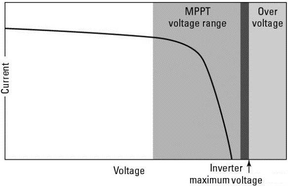
As you can see in Figure 1, the DC voltage window can be viewed in relation to the PV array in an IV curve. The goal is to keep the Voc portion of the IV curve below the maximum inverter voltage value and the Vmp portion within the operating voltage range. Each of the voltages gets adjusted based on temperature, so this window can actually become very narrow very quickly.
The minimum and maximum DC voltage values dictate the number of modules that can be placed in any string that’s connected to an inverter. Typically, the calculations I show you in the next two sections result in multiple string lengths — different numbers of modules you can place in series for proper inverter operation.
Most inverters have just a single maximum power point tracker installed. Unless you’re using an inverter that has multiple built-in maximum power point trackers, you must keep the strings of PV modules equal in size.
Therefore, if you calculate that an inverter can accept multiple strings of 11 modules or strings of 12 modules, all the strings must be either 11 or 12 modules in length. In other words, the string lengths must remain equal, or else the inverter can’t operate correctly.
Calculating the modules’ maximum DC voltage contribution: When working with the DC side of an inverter, I like to consider the inverter’s maximum DC voltage input first because providing too much voltage to the inverter can cause damage. You see, all inverters have capacitors inside them that act as shock absorbers. They accept the array’s power and are able to smooth out any bumps along the way, which means the capacitors are one of the very first things connected to the PV array. If too much voltage is connected to these capacitors, they’ll eventually become compromised and fail, meaning the inverter can’t ate.
You should also know that all inverters record the maximum voltage values ever seen by the inverter. So if you design or install your client’s system incorrectly and apply too much voltage to the inverter, that information will be recorded.
If your client sends the inverter in for a warranty repair, the manufacturer will check the stored data, see that the voltage was too high, and void your client’s warranty. This is an expensive mistake that can be easily avoided in both the design and installation processes.
As the temperature decreases, a PV module’s voltage actually increases (voltage and temperature therefore have an inverse relationship). To make sure an array’s voltage never exceeds the inverter’s input value, you need to adjust the modules’ STC open circuit voltage value (Voc) for cold temperatures; this value is reported on spec sheets.
The most common way to approach this problem is to look at the record cold temperature wherever the array is to be placed and adjust the modules’ open circuit voltage based on that temperature. By using the record cold temperature, you’re accounting for the fact that it takes very little irradiance to produce voltage from a module (irradiance is the intensity of the solar radiation striking the earth).
And because current won’t be flowing immediately (because the irradiance value is very small when the sun breaks over the horizon), the inverter will be connected to this initial high voltage.
In reality, this is a conservative approach because, a PV module reaches approximately 90 percent of its full voltage at 200 W/m². By the time the module is producing full voltage, the array has sufficient irradiance to produce current, and the voltage will automatically drop to maximum power voltage values.
The exact values are difficult to calculate accurately, so in all the calculations I show you in the following sections, I use the record cold temperatures and say that the voltage will jump to full open circuit voltage as soon as the sun breaks over the horizon each morning.
With that in mind, you’re ready to calculate a PV module’s adjusted open circuit voltage based on temperature. First things first: Keep the big picture in mind. You must determine the maximum voltage produced by the module based on the record cold temperatures and then use this adjusted voltage to determine the maximum number of modules you can place in a series string without exceeding the inverter manufacturer’s requirements for the maximum DC voltage input. I walk you through the process in the sections that follow.
Talking about temperature coefficients: In order to accurately calculate a PV module’s adjusted open circuit voltage, you need to know how the module’s manufacturer measures how its modules’ voltage values will react at temperatures less than and greater than the STC of 25 degrees Celsius. This number is known as a temperature coefficient, and it can be reported for both Voc and Vmp.
(Note: The two different voltage values have two different temperature coefficients, but many PV module manufacturers report only the temperature coefficient for Voc. When I get to adjusting the Vmp in the later “Crunching the numbers” section, I show you how to estimate this rarely provided coefficient fairly accurately.)
A typical Voc temperature coefficient value for crystalline modules is –0.35%/°C. This value indicates that for every degree change in the PV module’s temperature, the voltage changes by slightly more than a third of a percent.
The negative number in the coefficient is very important; it shows the verse relationship between temperature and voltage. (Keep in mind that –0.35%/°C is a close approximation for all crystalline PV modules, but it’s by no means an absolute value. As for thin film modules, the temperature coefficient values vary widely among technologies.)
According to STC, the base temperature for all PV modules is 25 degrees Celsius, so you have to look at the change in temperature as it relates to 25 degrees Celsius. For example, if the module is on a rooftop and the temperature at dawn is 15 degrees Celsius, the module’s voltage will be 10 degrees Celsius less than STC: 15°C – 25°C = –10°C (the negative sign indicates a temperature less than STC).
So if you were asked what the percentage change in voltage is due to temperature, you could run the numbers like so:
–10°C × –0.35%/°C = +3.5%, or a rise of 3.5%
Another way you may see temperature coefficients reported is as a certain number of volts per degree Celsius. The exact number is dependent on the Voc for a particular module and should only be used for that module.
To see what I mean, suppose an array was in a 15 degrees Celsius environment. If I told you that the temperature coefficient for the module was –0.158 V/°C, you could take that information and tell me how many volts the module would be reading off of the STC of 25 degrees Celsius:
15°C – 25°C = –10°C
–10°C × –0.158 V/°C = +1.58 V, or a rise of 1.58 V
You can use either value reported as long as you use them correctly in the equations. However, the second temperature coefficient mentioned, the number of volts per degree, is generally easier to visualize because you can imagine the numbers of a meter changing.
Working the steps: To determine the change in voltage due to temperature, you need to apply the temperature-adjustment equation. Here’s how to do just that:
- Collect the temperature coefficient for the PV module. You can find this information on the manufacturer-provided spec sheet that comes with the module.
- Collect the record cold temperature for your client’s location in degrees Celsius. The Web site weather.com is a great resource for this data.
- Calculate how many degrees Celsius less than STC the site will be on that record cold day.
- Multiply the temperature coefficient for the module by the number of degrees calculated in Step 3. The result of this equation is the change in voltage the module will produce.
- Add the number of volts calculated in Step 4 to the Voc for the module at STC.
What you’re left with is the adjusted maximum module voltage based on the area’s record cold temperature. To help you grow more at ease with the temperature-adjustment equation, try the following example. The PV module in question is a typical crystalline module located in a place that has a record cold temperature of –5° Celsius. The module specifications you need to collect are as follows:
Voc = 45.0 V
Temperature coefficient = –0.158 V/°C
At this point, you have all the information you need to determine the maximum voltage for this module at the area’s record cold temperature. Follow the previously outlined steps to find that
- The given temperature coefficient is –0.158 V/°C.
- The lowest recorded site temperature is –5°C.
- The number of degrees this temperature is from STC is –5°C – 25°C = –30°C.
- The voltage change is therefore –30°C × –0.158v/°C = +4.7 V.
- The adjusted module voltage is thus 45.0 V + 4.7 V = 49.7 V.
But what if the module manufacturer gives you the temperature coefficient in the percent per degree Celsius? The easiest thing to do is convert that percentage into a number of volts per degree Celsius by multiplying the percent per degree Celsius by the open circuit voltage. For example, if the module you’re using is rated at 45 Voc and the temperature coefficient is given as –0.35%/°C:
45 Voc × –0.35%/°C = 45 Voc × –0.0035/°C = –0.158 Voc/°C
The steps for working the temperature-adjustment equation can be used with any PV module so long as you find the temperature-adjustment data specific to the module manufacturer — the PV technology (crystalline versus thin film) doesn’t matter.
The different PV module technologies all have their own temperature- adjustment factors, which means you can’t swap the values of a crystalline module for those of a thin film module just because the manufacturer doesn’t supply the information. If you do, you’ll wind up with false information that may cause you to design and install a PV system that’ll damage the inverter on the first cold morning.
Using NEC info in a pinch: If you’re using a crystalline PV module, either single or multicrystalline, and the module manufacturer doesn’t supply a temperature coefficient, the NEC states that you can use the values presented in Table 690.7 (see Figure 2). This table allows you to look up a multiplier based on a temperature range and use that to determine the temperature-adjusted voltage.
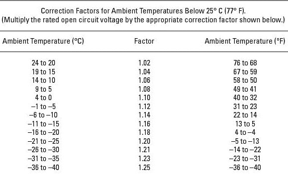
If, for example, you’re using a crystalline PV module with a Voc value of 45 V and the manufacturer doesn’t supply a temperature coefficient, you can turn to Table 690.7 in the NEC. If the record cold temperature is –5 degrees Celsius, just find –5 degrees Celsius in the table and look straight across to find the appropriate multiplier, which is 1.12.
To determine the temperature-adjusted maximum voltage, simply multiply the module Voc value at STC by the multiplier. Here’s what the equation looks like:
45 V × 1.12 = 50.4 V
Obviously, using the NEC table is a lot easier than performing the temperature-adjustment equation yourself. So why would you ever want to take the time to run the calculations when you can easily find what you need in the NEC table? Well, there are a few reasons:
- First off, Article 690.7 of the NEC has a requirement that when the information is provided from the manufacturer, “you shall calculate the new voltage.”
- Second, you may want to use thin film technology in the PV system you’re designing, in which case the table doesn’t even apply. If you’re using any PV technology other than crystalline, you have to use the calculations I show in the previous sections to determine the maximum voltage.
- Finally, the NEC will always be more conservative in its method. Therefore, relying solely on the table may result in a maximum voltage that doesn’t work well in the system you want to install.
Applying the adjusted open circuit voltage to come up with the right number of modules in a string: After you calculate the module’s temperature-adjusted voltage, you need to see how that temperature-adjusted voltage will affect the number of modules you can place in any one string that will connect to your grid-direct inverter.
As I explain earlier in this chapter, every inverter has a maximum allowable voltage it can receive from the array. For grid-direct inverters, this value typically ranges from 500 VDC to 600 VDC, although it can be even lower than that (the maximum allowable voltage really depends on the components used by the inverter manufacturer).
To determine the maximum number of modules you can place in a series string, you need to look up the maximum input voltage from the spec sheet of an inverter you’re thinking about using and divide that value by the module’s maximum Voc value (which you calculated based on the record cold temperature in the area).
Say you want to use an inverter that has a 600 VDC maximum input value and you select the temperature-adjusted module Voc from the earlier “Working the steps” section. You can calculate the maximum number of modules like so:
600 VDC ÷ 49.7 V = 12.07
This equation tells you that you can place 12.07 modules in a string without exceeding the 600 V rating of the inverter. But because you can’t buy fractions of a module, you have to round this number down to the nearest whole number, which is 12 modules.
Note: I used the maximum voltage I calculated in this example, but you can also run the numbers by using the maximum voltage you find with the help of the NEC table in the earlier “Using NEC info in a pinch” section. To save you flipping some pages, that voltage was 50.4 V. If 50.4 V was in fact the correct adjusted voltage, the maximum number of modules you could place in a series string would be
600 VDC ÷ 50.4 V = 11.9
In this case, you have to round down to 11 modules in a string. If you were to round up to 12, the 600 V value would be exceeded, and you’d run the risk of killing the inverter. This is an example of why taking the time to perform all the calculations can be beneficial: The array using 11 modules in a string may not be the best scenario for your client’s installation, and having the ability to add an extra module could make a big difference.
At this point, all you’ve done is define the maximum number of modules you can place in a string. You haven’t necessarily determined the right number of modules for the system because the number of modules in a string doesn’t need to exactly match the physical layout of any one row or column of modules. Therefore, you must repeat this process for voltage loss due to high temperatures and then use that info, combined with the initial criteria you established — the client’s budget, the available area, and so on — to define the whole array.
Figuring out the modules’ minimum DC voltage contribution: On the other end of the voltage window is the minimum power point tracking voltage. If the voltage from the array ever drops below this value — usually due to high heat conditions that occur on the sunniest days (as in the days system owners expect their arrays to produce the maximum amount of energy possible) — the inverter won’t be able to continue operating and will shut down. Although this scenario won’t damage the inverter, it may damage your reputation.
If your client sees his inverter shut down on a bright, sunny day because the voltage isn’t high enough, expect to have a not-so-pleasant conversation with him (and possibly lose recommended business from your client if you can’t salvage his opinion of your work).
A PV module’s voltage decreases as the temperature increases, which means that in the heat of the day — while the array is operating — the modules’ voltage will be reduced. In this situation, you need to look at the maximum power voltage, Vmp, and make adjustments from there because the array will be operating and the voltage will be reduced from the Vmp value. I explain what you need to do in the next sections.
Keeping long-term performance considerations in mind: PV modules are great and can perform for many years, but they aren’t perfect. The typical power output warranty for a module says that the manufacturer guarantees that the module will produce at least 80 percent of its original power output in 25 years. This verbiage means that over the course of 25 years, the module’s power output will be reduced by less than 1 percent per year — at the expense of both voltage and current over the course of the module’s life. Being aware of this voltage loss is critical because voltage is so important when matching PV arrays to inverters.
So what does long-term voltage loss mean to you as you go about sizing systems? Simple. You don’t want to design a PV array for connection to an inverter that barely fits inside the voltage window today. For example, if an inverter needs 250 VDC to operate, you don’t want to design your PV array to operate at 255 VDC at the hottest time of the year starting in the first year. If you do, you’re not allowing for much voltage degradation before the array can’t keep up with the inverter’s requirements.
In the next few sections, I show you how to calculate the minimum number of modules you need to place in a string to allow the inverter to operate when the module temperature is elevated. When you go through these steps and arrive at the minimum number of modules needed, add one module to that value and consider that your minimum (unless of course adding one module makes you have too many modules in a string; see the previous section for more on that).
By adding just one module, you build in protection against falling out of the inverter’s voltage window due to natural degradation, thereby preserving the long-term performance of the system.
Picking the temperature to use in your math: Just like you need to calculate the adjusted Voc for the record cold temperatures, you need to calculate the adjusted Vmp for hot temperatures. But which hot temperature should you use? After all, the NEC doesn’t have any requirements when it comes to keeping an array above an inverter’s minimum voltage because you can’t cause any damage with a low-voltage scenario like you can when too much voltage is applied. You also can’t rely on a table to tell you the multiplier value because no such table exists.
Here’s what to do: Start by defining the ambient summertime temperature, which is the high temperature at the array location during the summer. Then increase the estimated module voltage above the ambient temperature based on the method used to hold the PV array.
You have to know how to use the temperature-adjustment equation I present in the earlier “Working the steps” section. The method used to calculate an array’s voltage in hot weather is exactly the same as for cold weather; you merely use different numbers. Here are your ambient temperature options:
The average high summertime temperature for the array’s location: If you use the average high summertime temperature for the array’s location, you’ll design around a realistic value that’ll be reached often. Then again, there’ll be many days of the year that the average high temperature is exceeded.
If you use the average high temperature and don’t allow for those extremely hot days, the array may just turn off on those record hot days.
The record high temperature: By designing with the record high temperature in mind, you ensure that the PV array will operate in all conditions, which isn’t a bad situation in my opinion. On the other hand, using the record high temperature can lead to overly conservative arrays because the calculated voltage loss is on the extreme end and doesn’t really happen on a regular basis.
The American Society of Heating, Refrigerating, and Air-Conditioning Engineers’ (ASHRAE) 2-percent design temperature: This is the value that I like to use. ASHRAE’s 2-percent design temperature says that for the given site, the temperature rises above the reported value only 2 percent of the time.
In other words, 98 percent of the time, the temperature is less than or equal to the number given. Using this value allows you to design for nearly every situation without requiring excessive calculations.
In 2009, Solar ABCs, a group that advocates for the solar industry on a wide variety of topics, released a document titled “Expedited Permit Process for PV Systems.” In this document, Solar ABCs publishes the average 2 percent temperature data for June through August for a number of cities across the United States.
This resource (found at www.solarabcs.org/permitting/Expermitprocess.pdf) gives you a quick reference for the 2-percent data.
Accounting for mounting in your math: After you know which hot temperature you intend to use for your calculations, you need to consider how you plan to mount the PV array because the mounting method affects the module’s temperature. To account for the mounting method, add a certain number of degrees to the ambient temperature based on the array’s proximity to a mounting surface.
The values shown in this section are estimates based on measurements made at multiple locations over a number of years. They can be used in the design process and represent rises in a PV module’s temperature at the hottest time of the year.
To estimate a PV module’s temperature at the hottest time of the year, you should add one of the following temperatures to the ambient temperature:
- 35 degrees Celsius for arrays with fewer than 6 inches between the backs of the modules and the mounting surface
- 30 degrees Celsius for arrays with more than 6 inches between the back of the array and the mounting surface
- 25 degrees Celsius for arrays that are mounted on top of a pole
By adding these values to the ambient temperature, you can arrive at a best estimate for your array’s operating temperature — the temperature you expect to see at the module level if you were to measure the temperature in the middle of the summer.
Crunching the numbers: When you know the temperature you’re going to estimate for the modules when they’re operating in the summer, you can begin the process of adjusting the Vmp value. To do so, you need to apply a specific temperature coefficient to the Vmp as the array grows hotter.
PV module manufacturers often report the temperature coefficient for Voc, but they rarely provide it for Vmp. Also, they almost all universally report the temperature coefficient for power. Although voltage isn’t the only factor affecting the temperature coefficient for power, it’s what affects it the most.
Therefore, if the module manufacturer doesn’t supply a temperature coefficient for voltage, I suggest taking the value reported for power and substituting it for the voltage coefficient. Doing so results in slightly more conservative values when it comes to the adjusted voltage, but your numbers will be reasonably close to the exact answer (and in most scenarios, the end result will be exactly the same).
For crystalline modules, the coefficient for power (and unless specified otherwise, for voltage) is very close to –0.5%/°C, which is a slightly greater change when compared to the coefficient that applies to Voc.
Here’s how to apply all the factors when calculating the adjusted Vmp values for your modules:
- Collect the temperature coefficient for your PV module in volts per degrees Celsius.
- Collect the 2-percent design temperature for your client’s location in degrees Celsius.
- Determine how many degrees Celsius to add to the ambient temperature based on how you plan to mount the array.
- Add the ambient and mounting method temperatures to estimate the operating temperature of the array in the summertime.
- Calculate how many degrees Celsius greater than STC the modules will be on 98 percent of the days.
- Multiply the temperature coefficient for the module by the number of degrees calculated in Step 5. The result of this equation is the change in voltage that the module will produce.
- Add the number of volts calculated in Step 6 to the Vmp for the module at STC.
Because the Step 6 number will always be negative, you must subtract the calculated value instead of adding it in order to find the adjusted maximum module voltage based on that temperature.
Suppose the Vmp for a particular module is 37.2 V and the manufacturer reports that the temperature coefficient for power is –0.5%/°C. Because the manufacturer doesn’t provide the temperature coefficient for voltage, you must apply the power coefficient to the voltage.
To calculate the number of volts per degree Celsius, multiply the coefficient by the Vmp.
37.2 V × –0.5%/°C = 37.2 V × –0.005/°C = –0.186 V/°C
The array location has an ASHRAE 2-percent design temperature of 33 degrees Celsius, and the array will be mounted parallel to a roof with only 4 inches of space between the roof and the backs of the modules. Apply this information to the preceding steps to get the following:
- The reported temperature coefficient is –0.5%/°C.
- The ambient design temperature is 33°C.
- The altered ambient temperature (to accommodate the mounting method, which calls for fewer than 6 inches between the backs of the modules and the mounting surface) is 68°C (33°C + 35°C = 68°C), the estimated module temperature when the array is operating.
- The number of degrees off of STC is therefore 68°C – 25°C = 43°C.
- The voltage loss due to temperature is thus 43°C × –0.186 V/° = –8.0 V.
- The new adjusted voltage for the module at the design temperature is therefore 37.2 V + –8.0 V = 37.2 V – 8.0 V = 29.2 V.
As you can see, the loss of voltage will be 29.2 V in the summertime — that’s pretty significant. If you continue to look at how the voltage will be reduced as the module ages, you’ll soon recognize the importance of keeping an eye on this calculation in the design process.
Totaling the minimum number of modules needed in a string: After you have the adjusted Vmp value, you can calculate the minimum number of modules needed in any string in order to operate the inverter. Continuing with the earlier example, if the inverter you’re thinking about using has a minimum input of 250 VDC, the minimum number of modules necessary will be that minimum voltage divided by the temperature-adjusted module voltage.
250 VDC ÷ 29.2 V = 8.56, or 9 modules minimum
Although this calculation defines the absolute minimum number of modules needed to keep the inverter running, a good practice is to make your mimum number of modules be the calculated number plus one. This practice gives you plenty of room for degradation and allows for the array to operate significantly hotter than anticipated and still keep the inverter running. So I’d want to use at least 10 modules in the strings for the earlier example.