Basic Thermocouple Circuits
Conventional electric circuit schematics represent passive conductors that often all are of copper. Distinctively, in thermoelectric circuits, paired legs are of very different materials and the “conductors” are the emf sources. Much more is involved than circuit connectivity.
True thermoelectric schematics must explicitly acknowledge each leg material, all junctions, essential relative junction temperatures, and any complementary voltage sources, as these all affect the Seebeck emf and net thermocouple voltage.
Seebeck’s Circuit
Inappropriately, the thermocouple is sometimes defined essentially as a closed circuit of two dissimilar thermoelements joined at two junctions, a “hotter” junction and a “colder” junction, as studied by Seebeck.
Based on this unbroken circuit, the Seebeck effect has been wrongly characterized as the occurrence of current in the closed loop, as was electromagnetically observed by Seebeck rather than properly as thermally caused emf.
The net Seebeck source emf is indeed proportional to the temperature difference between the two junctions and to a relative coefficient for the paired materials, but that emf results in loop current and IR voltage loss in the typically high-resistance thermocouple circuit. That significantly reduces the net voltage.
The Seebeck emf for accurate thermometry should be measured in “open-circuit” mode that suppresses current by monitoring with an instrument of relatively large input resistance (e.g., greater than 10 kΩ). In practical thermometry, no applied thermoelectric circuit has only two dissimilar materials or only two junctions.
Typical thermometry circuits have many materials and junctions. Several incidental junctions, if not temperature controlled, can result in significant unrecognized spurious Seebeck emf and error.
In each of the two following basic thermocouple circuits, a particular electrical circuit connectivity, but with different materials and temperature distributions, results in very different thermoelectric characteristics and error sources.
Dual-Reference Junction Circuit
A generalized form of the circuit that is most commonplace in practical thermocouple thermometry (Figure 2.1) involves a single measuring junction and one essential pair of isothermal temperature reference junctions. Most applied thermocouples also have one or more optional extensions. Two are shown. This circuit is used in most thermometry applications.
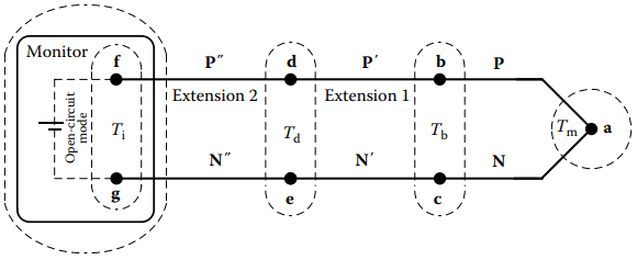
The primary, measuring, thermocouple is a pair of thermoelements, P and N, that are joined at a single measuring junction, a. Legs P and N must have different Seebeck coefficients. The coefficients of either or both can be of either positive or negative polarity
Reference Temperature Compensation
In thermometry, the reference junctions usually are not at the 0 °C reference temperature. Complementary compensation voltage to effect the 0 °C reference temperature is applied internally by the monitor or by an external compensator.
(Note that, the internal circuitry of the monitoring instrument—and of any compensator—unavoidably is itself a complex thermoelectric network that also contributes an indefinite varying Seebeck voltage unless, after warm-up, it remains stable at sufficiently uniform temperature.)
Types of Optional Extension
To decrease the length of this web-page, content of this section is placed on another page. To access that page, please follow the link.
Single-Reference Junction Circuit
Another practical circuit form, Figure 2.2, combines two separate thermocouples and their connectors. The measuring thermocouple is PN. The reference thermocouple is P′N′.
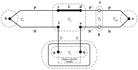
The reference thermocouple often is a commercially fabricated assembly that includes the several components ending with connector terminals, d and e. The connector of measuring thermocouple PN (or any emf-contributing extensions, as P″N″) plugs into the reference at d and e.
For calibration, extensions should not be used between the measuring thermocouple assembly and the reference thermocouple assembly. If extensions are used, they must never be of passive type.
This circuit is commonly used for convenience in routine calibration laboratories where it is desired to physically impose a controlled and precisely known reference temperature on junction b. (For accurate calibration, the circuit of Figure 2.1 with passive-style extension is less subject to hidden error, particularly near ambient temperature.)
Typically, in circuits like Figure 2.2, the measuring thermocouple and reference thermocouple are separately acquired thermocouple assemblies. The two thermocouples likely have significantly different Seebeck characteristics even if they are nominally of the same thermocouple type.
The calibration of the reference thermocouple initially should be confirmed around room temperature but often it is not. For Tm near ambient temperature, much of the emf is from the reference thermocouple—not from the measuring thermocouple. Therefore, reported calibration of a measuring thermocouple, with contribution from the reference, is misleading at all temperatures.
Only if connector link L is isothermal, it may be of any material, inhomogeneity, length, or temperature, Tc. The input terminals g and h of the monitoring instrument may be of any isothermal temperature, Ti . The reference temperature is physically applied and only at b. The monitoring instrument must not also apply compensation voltage for temperature Ti of the instrument junctions.
Differential Thermocouple Thermometer
The temperature difference between two points often is of interest. The difference emf of a pair of thermocouples of the same type connected in series opposition provides a direct indication of temperature difference. However, the difference emf depends nonlinearly on the temperatures.
Examples: standard values of emf for the same 100 °C temperature difference of a differential Type T thermocouple are

The emfs, therefore the deduced difference temperatures, would significantly disagree. Accurate scaling of emf to temperature would require applying separate nonlinear scaling relations for a known temperature of the thermocouple type.
For accuracy, some monitors instead provide dual sets of input terminals for simultaneous monitoring of a pair of thermocouples of the same type. Either of the measured temperatures is displayed along with the accurate calculated temperature difference.
Related Posts
- Thermocouple Working Principle
- Absolute Seebeck Effect
- Basic Thermocouple Circuits
- Extensions of Thermocouple
- Functional Model of Thermoelectric Circuits
- T/X Sketch of Dual-Reference Junction Circuit
- Applications of Functional Model
- Characteristics of Thermocouples
- Thermocouple Hardware
- Thermocouple Junction Styles
- Active Tests of Thermocouple
- Calibration of Thermocouples
- Thermocouple Thermometry Practice
- Distinctive Thermocouple Noise Problems