A very common application of transistors is to construct drivers to drive motors. One such circuit is the H-bridge driver circuit, which is commonly used to drive motors in both directions. The circuit looks like the letter ‘H’ in circuit schematics, so it is called an H-bridge.
An H-bridge circuit is constructed using four switching elements that are situated at the corners of the ‘H’ as the main components. The switching elements used are transistors. The transistors can be of the BJT type or MOSFET type, but depending on the transistors used, the circuit will have different power ratings.
Operation of H-Bridge Circuit
To understand the operation of H-bridge circuit, consider first the simple schematic shown in Figure 1, which shows four switches connected to a DC motor.
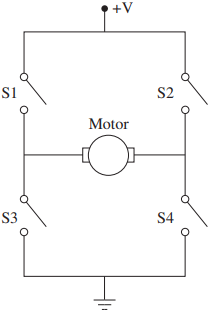
Let us assume that for this motor to turn clockwise, a positive voltage needs to be applied to the left lead, and the right lead should be grounded. This can be achieved by closing switches 1 and 4 and keeping switches 2 and 3 open.
This causes current to flow from the power source to ground through switch 1, the motor leads, and switch 4.
If we want to rotate the motor in a counterclockwise fashion, then switches 2 and 3 should be closed, and switches 1 and 4 should be open. This reverses the voltage polarity across the motor and causes the motor to rotate in the opposite direction.
Obviously, closing switches 1 and 3 or 2 and 4 at the same time should not be done, as this will lead to a short circuit.
implementation using DPDT relays.
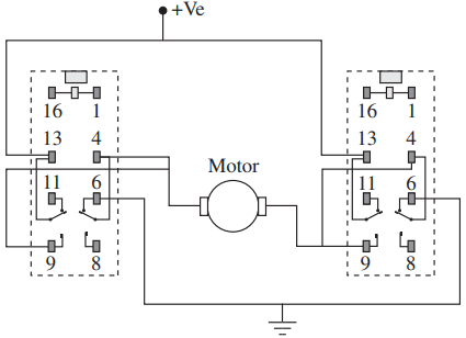
Figure 2 shows an implementation of the H-bridge circuit using the G5V-2 Omron® relay as the switching element. The wiring for the relay coil is not shown in the figure. Notice that using two relays, there are four states of operation for this circuit.
When both relays are OFF, the switch configuration is as shown in the figure, and the motor will not operate. Similarly, if both relays coils are ON, the motor still will not operate.
In the third state when the left relay is ON and the right relay is OFF, the motor will rotate in one direction. In this case, a positive voltage is applied to the left lead of the motor through pin #9 on the left relay, while the right lead of the motor is grounded through pin #6 on the right relay.
In the fourth state, the left relay is OFF, and the right relay is ON. The polarity of the voltage applied to the motor will be opposite to that of state three, and the motor will rotate in the opposite direction.
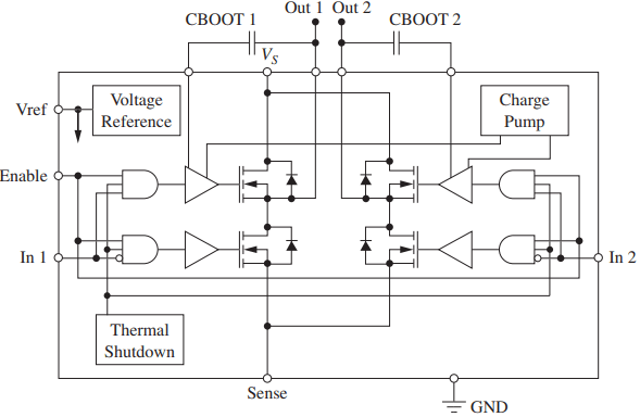
While Figure 2 shows how an H-bridge can be implemented using electromechanical relays, typical H-bridge circuits are implemented using transistors due to the fast switching time of transistors compared to electromechanical relays. Figure 3 shows such an implementation using MOSFET power transistors.
Operation of L6203 H-bridge Circuit
This L6203 chip from ST Microelectronics supplies up to 1 A current, which is enough to drive small brush type DC motors. The supply voltage can be up to 48 V. The L6203 H-bridge operates as follows.
L6203 H-bridge.
There are two input signals IN1 and IN2 and one ENABLE input signal. The IN1 and IN2 signals are used to select the particular leg of the H-bridge. The ENABLE input has to be high for the H-bridge to operate. The motor leads are connected to OUT1 and OUT2 leads.
- If IN1 is high and IN2 is low, OUT1 will be at the supply voltage (Vs), and OUT2 will be grounded. In this case, the upper-left and lower-right transistors will be conducting, and the upper-right and lower-left transistors will not be conducting.
- Similarly, if IN1 is low and IN2 is high, OUT1 will be grounded, and OUT2 will be at the supply voltage (Vs), thus reversing the polarity of the voltage supplied to the motor.
Notice that the chip has a temperature-sensor circuit that shuts down the H-bridge if the temperature exceeds a preset value (typically 150°C).
The flyback diode that is placed between the source and drain leads of the MOSFET transistor is called an intrinsic diode and is built-in as part of the transistor. Its purpose is to protect the transistor when the transistor switches its state with inductive loads attached to the chip.
H-bridge drives are used to control various types of actuators, including brush DC, brushless DC, and stepper motors. H-bridge drivers are typically packaged with additional components to produce what is called a servo drive, which is used in controlling actuators.