Most commercial servo drives accept PWM and direction signals as input. Also, many servo drives produce a PWM output voltage signal to the load such as a motor coil instead of a linearly variable output voltage.
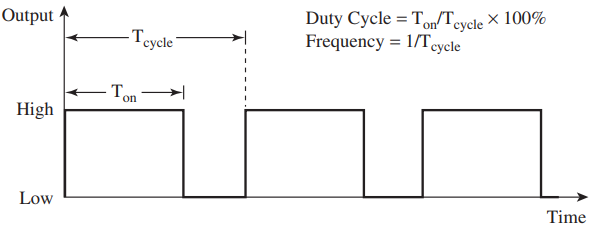
A PWM signal is a square-wave signal of fixed amplitude and frequency, but the width of the on and off parts of the signal (or duty cycle) can be varied (see Figure 1).
PWM Control of DC Motors
PIC MCUs have a built-in module to generate pulsewidth modulated (PWM) output. One can set the parameters of the PWM signal using a PIC MCU. The PWM output can be used to conveniently drive H-bridge drives and digital amplifiers.
The duty cycle of a PWM voltage signal corresponds to the average voltage delivered to the load. For example, if the amplitude of the PWM signal is 12 V, then at a 25% duty cycle, an average voltage of 3 V is delivered to the load. Similarly, at 75% duty cycle, an average voltage of 9 V is delivered to the load.
Normally, the PWM signal pulse period is much smaller than the time constant of the actuated load, so the load does not respond to each ON and OFF portion of the PWM signal but to the average value of the PWM signal.
There are actually two methods of using PWM signals in motor control. The first is called the sign-magnitude method and the other is called the locked antiphase method.
Sign Magnitude Method
In the sign-magnitude method, the controller (such as a PIC MCU) provides two signals: a PWM signal to control the magnitude of the voltage supplied to the load and a digital two-level signal to control the direction or sign.
In the sign-magnitude method, the higher the duty cycle of the PWM signal, the higher the average voltage (or magnitude) delivered to the load. At 0% duty cycle, no voltage is supplied to the load, while at 100% duty cycle, the full voltage signal is supplied to the load.
For example, the sign-magnitude method can be used to drive the servo drive AZ6A8DDC or an H-bridge driver such as the L6203.
In using the L6203 bridge driver, additional circuitry is needed to interface the sign and magnitude signals to the IN1, IN2, and ENABLE leads.
Locked Anti-phase Method
In the locked anti-phase method, a single PWM signal is used to control the voltage delivered to the load and the direction of rotation.
In this method, opposite pairs of switches in an H-bridge circuit (such as S1 and S4 or S2 and S3 alternate between being ON and OFF according to the duty cycle.
If the duty cycle is 50%, the opposite pairs of switches in the H-bridge circuit will close for the same duration in each PWM cycle, resulting in the net voltage applied to the motor leads to be zero and hence no rotation of the motor. If the duty cycle is 60% for example, then a net 20% (60% 40%) of the available voltage is applied to the motor leads in each PWM cycle.
The direction of rotation is set by which motor lead has more positive net voltage in each cycle.
Thus when the duty cycle is less than 50%, then the motor will rotate in one direction, and when the duty cycle is above 50%, the motor will rotate in the opposite direction.
At both 0 and 100% duty cycles, the maximum voltage is applied to the motor in each case but in opposite directions.
On advantage of the locked anti-phase method is that a single control signal is used to control the speed and direction of a motor load. A disadvantage of this method is that it creates more ripple currents in the motor.
In servo drives (such as AZ6A8DDC) or H-bridge drives (such as LMD18200) with dedicated direction and PWM input lines, the PWM input line is wired to high logic, and the PWM control signal is applied to the direction line in using the locked anti-phase drive method.
For the L6303 H-bridge driver, it is wired using the locked anti-phase drive method.
Servo Drives for PWM Control of DC Motors
For motion control applications, servo drives or amplifiers are used to amplify the reference signal sent to the actuator since they place in one convenient package all the components needed to amplify the input signal.
Drives can be broadly classified as digital or analog. Digital drives can take input signals in various forms such as analog, digital (step and direction or PWM and direction), RS-232, or through an Ethernet connection, while analog drives take as an input analog (+/- 10 VDC such as that supplied by a D/A converter) or PWM and direction signals.
In a digital drive, the drive is configured using a software program running on a PC, while an analog drive is configured using switches and potentiometers.
Analog amplifiers can be further classified as brush or brushless amplifiers, referring to the type of electric motor that they can drive. Brush-type analog amplifiers are designed to drive brush-type DC motors, and other inductive-type loads such as voice-coil motors, and magnetic bearings.
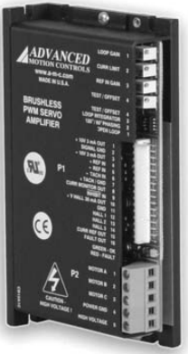
An example of an analog, brush-type amplifier is the 12A8 amplifier made by Advanced Motion Controls is shown in Figure 2. This amplifier is suitable for driving small motors, takes 10 VDC as input, is rated at 24 W, and uses an H-bridge circuit for the amplification. It requires a single unregulated DC power supply that can supply a DC voltage in the range of 20 to 80 V.
This amplifier allows the user to adjust the following parameters using 14-turn potentiometers: loop gain, current limit, input gain and offset.
Loop Gain: The loop gain factor when the amplifier is operated in the voltage or velocity mode.
Current Limit: The peak and continuous current that can be supplied by the amplifier. When the current limit is adjusted, the ratio of the continuous to peak current is maintained.
Input Gain: The ratio between the output variables (voltage, current, or velocity) and the input signal.
Offset: A signal that can be used to adjust any imbalance in the input signal or the amplifier output.
This amplifier can operate in various modes including voltage, velocity, and current (torque) modes.
In voltage mode, the amplifier produces an output voltage signal that is proportional to the input voltage signal regardless of variation in the supply power. The output amplification or loop gain is variable and set by adjusting the Loop Gain pot.
In velocity mode, the amplifier supplies a voltage to maintain the motor at a specific speed. For this mode, the amplifier uses the actual motor speed, as measured by the tachometer that is attached to the motor shaft, as a feedback signal.
In current mode, the amplifier produces an output current signal to the motor. Because the output torque of DC motors is proportional to the input current, the current operation mode is sometimes referred to as torque mode.
This amplifier, like many other commercial servo amplifiers, gives a high frequency (36 kHz) pulse width modulated output (or PWM output). Rather than changing the amplitude of the output signal, a PWM amplifier varies the duty cycle of fixed-amplitude, fixed-frequency signal as means of modulating the output power.
This results in a very efficient way to deliver power to the load since it reduces the power lost in the output stage of the drive.
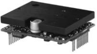
Another analog drive that is suitable for driving small motors is shown in Figure 3. This drive takes only PWM and direction signals as input, and thus, it is very suitable to be interfaced to microcontrollers, many of which can provide this type of output.
the AZ6A8DDC drive.
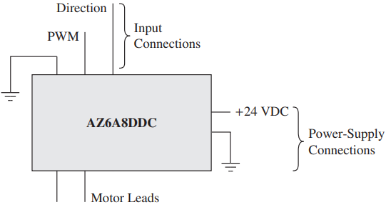
Figure 4 shows the minimum wiring needed to drive a motor using this amplifier. The amplifier has other connections (such as current output monitor, fault output, and inhibit line), but these do not need to be connected for the amplifier to operate, and thus are not shown.