Data manipulation involves transferring data and operating on data with math functions, data conversions, data comparison, and logical operations. This article covers both data manipulation instructions that operate on word data and those that operate on file data, which involve multiple words.
Data manipulations are performed internally in a manner similar to that used in microcomputers. Examples of processes that need these operations on a fast and continuous basis are studied.
Data Manipulation Instructions in PLC
Data manipulation instructions allow numerical data stored in the controller’s memory to be operated on within the control program. This category of word operation instructions allows the user to truly exploit the computer capabilities of the PLC. The use of data manipulation extends a controller’s capability from that of simple on/off control based on binary logic, to quantitative decision making involving data comparisons, arithmetic, and conversions—which in turn can be applied to analog and positioning control.
There are two basic classes of instructions to accomplish data manipulation: instructions that operate on word data and those that operate on file, or block, data, which involve multiple words. Each data manipulation instruction requires two or more words of data memory for operation. The words of data memory in singular form may be referred to either as registers or as words, depending on the manufacturer. The terms table or file are generally used when a consecutive group of related data memory words is referenced.
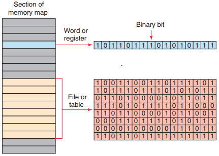
Figure 1 illustrates the difference between a word and a file. The data contained in files and words will be in the form of binary bits represented as series of 1s and 0s. A group of consecutive elements or words in an AllenBradley SLC 500 are referred to as a file. The data manipulation instructions allow the movement, manipulation, or storage of data in either single- or multiple-word groups from one data memory area of the PLC to another.
Use of these PLC instructions in applications that require the generation and manipulation of large quantities of data greatly reduces the complexity and quantity of the programming required. Data manipulation can be placed in two broad categories: data transfer and data comparison. The manipulation of entire words is an important feature of a programmable controller.
This feature enables PLCs to handle inputs and outputs containing multiple bit configurations such as analog inputs and outputs. Arithmetic functions also require data within the programmable controller to be handled in word or register format.
To simplify the explanation of the various data manipulation instructions available, the instruction protocol for the Allen-Bradley SLC 500 families of PLCs will be used. Again, even though the format and instructions vary with each manufacturer, the concepts of data manipulation remain the same.

Figure 2 shows the Move/Logical menu tab for the SLC 500 PLC and its associated RSLogix software. The commands can be summarized as follows:
- MOV (Move): Moves the source value to the destination.
- MVM (Masked Move): Moves data from a source location to a selected portion of the destination.
- AND (And): Performs a bitwise AND operation.
- OR (Or): Performs a bitwise OR operation.
- XOR (Exclusive Or): Performs a bitwise XOR operation.
- NOT (Not): Performs a bitwise NOT operation.
- CLR (Clear): Sets all bits of a word to zero.
Data Transfer Operations
Data transfer instructions simply involve the transfer of the contents from one word or register to another. Figure 3 a and b illustrate the concept of moving numerical binary data from one memory location to another.

Figure 3 a shows the original data are in register N7:30 and N7:20. Figure 3 b shows that after the data transfer has occurred register N7:20 now holds a duplicate of the information that is in register N7:30. The previously existing data stored in register N7:20 have been replaced with those of N7:30. This process is referred to as writing over the existing data.
Data transfer instructions can address almost any location in the memory. Prestored values can be automatically retrieved and placed in any new location. That location may be the preset register for a timer or counter or even an output register that controls a seven-segment display.
SLC 500 controllers use a block-formatted move (MOV) instruction to accomplish data moves. The MOV instruction is used to copy the value in one register or word to another. This instruction copies data from a source register to a destination register.

Figure 4 shows an example of the MOV instruction. The operation of the program can be summarized as follows:
- When the rung is true, input switch A closed, the value stored at the source address, N7:30, is copied into the destination address, N7:20.
- When the rung goes false, input switch A opened, the destination address will retain the value unless it is changed elsewhere in the program.
- The source value remains unchanged and no data conversion occurs.
- The instruction may be programmed with input conditions preceding it, or it may be programmed unconditionally.
The move with mask (MVM) instruction differs slightly from the MOV instruction because a mask word is involved in the move. The data being moved must pass through the mask to get to their destination address. Masking refers to the action of hiding a portion of a binary word before transferring it to the destination address. The operation of a mask word can be summarized as follows:
- The pattern of characters in the mask determines which source bits will be passed through to the destination address.
- The bits in the mask that are set to zero (0) do not pass data.
- Only the bits in the mask that are set to one (1) will pass the source data through to the destination.
- Bits in the destination are not affected when the corresponding bits in the mask are zero.
- The MVM instruction is used to copy the desired part of a 16-bit word by masking the rest of the value.

Figure 5 shows an example of a mask move (MVM) instruction. This instruction transfers data through the mask from the source address, B3:0, to the destination address, B3:4. The operation of the program can be summarized as follows:
- The mask may be entered as an address or in hexadecimal format, and its value will be displayed in hexadecimal.
- Where there is a 1 in the mask, data will pass from the source to the destination.
- Where there is a 0 in the mask, data in the destination will remain in their last state.
- Status in bits 4–7 are unchanged due to zeroes in the mask (remained in their last state).
- Status in bits 0–3 and 8–15 were copied from the source to destination when the MVM instruction went true.
- The mask must be the same word size as the source and destination.
The bit distribute (BTD) instruction is used to move bits within a word or between words, as illustrated in Figure 6 .

On each scan, when the rung that contains the BTD instruction is true, the processor moves the bit field from the source word to the destination word. Bits are lost if they extend beyond the destination word; the bits are not wrapped to the next higher word.
To move data within a word, enter the same address for the source and destination. The source data will remain unchanged but the instruction writes over the destination with the specified bits.

The program of Figure 7 illustrates how the move (MOV) instruction can be used to create variable preset timer values. A two-position selector switch is operated to select one of two preset timer values. Operation of the program can be summarized as follows:
- When the selector switch is in the open 10 s position, rung 2 has logic continuity and rung 3 does not.
- As a result, the value 10 stored at the source address, N7:1, is copied into the destination address, T4:1.PRE.
- Therefore, the preset value of timer T4:1 will change from 0 to 10.
- When pushbutton PB1 is closed, there will be a 10 s delay period before the pilot light is energized.
- When the selector switch is in the closed 5 s position, rung 3 has logic continuity and rung 2 does not.
- As a result, the value 5 stored at the source address, N7:2, is copied into the destination address, T4:1. PRE.
- Closing pushbutton PB1 will now result in a 5 s time-delay period before the pilot light is energized.

The program of Figure 8 illustrates how the move (MOV) instruction can be used to create variable preset counter values. The operation of the program can be summarized as follows:
- Limit switch LSI is programmed to the input of up-counter C5:1 and counts the number of parts coming off a conveyor line onto a storage rack.
- Three different types of products are run on this line.
- The storage rack has room for only 300 boxes of product A or 175 boxes of product B or 50 boxes of product C.
- Three momentary switches are used to select the desired preset counter value depending on the product line (A, B, or C) being manufactured.
- A reset button is provided to reset the accumulated count to 0.
- A pilot lamp is switched on to indicate when the storage rack is full.
- The program has been constructed so that normally only one of the three switches will be closed at any one time. If more than one of the preset counter switches is closed, the last value is selected.
A file is a group of related consecutive words in the data table that have a defined start and end and are used to store information. For example, a batch process program may contain several separate recipes in different files that can be selected by an operator. In some instances it may be necessary to shift complete files from one location to another within the programmable controller memory.
Such data shifts are termed file-to-file shifts. File-to-file shifts are used when the data in one file represent a set of conditions that must interact with the programmable controller program several times and, therefore, must remain intact after each operation.
Because the data within this file must also be changed by the program action, a second file is used to handle the data changes, and the information within that file is allowed to be altered by the program. The data in the first file, however, remain constant and therefore can be used many times.

Other types of data manipulation used with file instructions include word-to-file and file-to-word moves, as illustrated in Figure 9. Files allow large amounts of data to be scanned quickly and are useful in programs requiring the transfer, comparison, or conversion of data. Most PLC manufacturers display file instructions in block format on the programming terminal screen.
Data Manipulation Instructions in PLC

Figure 10 compares the SLC 500 controller word and file addressing. The addressing formats can be summarized as follows:
- The address that defines the beginning of a file or group of words starts with the pound sign #.
- The # prefix is omitted in a single word or element address.
- Address N7:30 is a word address that represents a single word: word number 30 in integer file 7.
- Address #N7:30 represents the starting address of a group of consecutive words in integer file 7. The length is eight words, which is determined by the instruction where the file address is used.
The file arithmetic and logic (FAL) instruction is used to copy data from one file to another and to do file math and file logic. This instruction is available only on AllenBradley PLC-5 and ControlLogix platforms. An example of the FAL instruction is shown in Figure 11 .

The basic operation of the FAL instruction is similar in all functions and requires the following parameters and PLC-5 addresses to be entered in the instruction:
Control
- Is the first entry and the address of the control structure in the control area (R) of processor memory.
- The processor uses this information to run the instruction.
- The default file for the control file is data file 6.
- The control element for the FAL instruction must be unique for that instruction and may not be used to control any other instruction.
- The control element is made up of three words.
- The control word uses four control bits: bit 15 (enable bit), bit 13 (done bit), bit 11 (error bit), and bit 10 (unload bit).
Length
- Is the second entry and represents the file length.
- This entry will be in words, except for the floating-point file, for which the length is in elements. (A floating-point element consists of two words.)
- The maximum length possible is 1000 elements. Enter any decimal number from 1 to 1000. Position
- Is the third entry and represents the current location in the data block that the processor is accessing.
- It points to the word being operated on.
- The position starts with 0 and indexes to 1 less than the file length.
- You generally enter a 0 to start at the beginning of a file. You may also enter another position at which you want the FAL to start its operation.
- When the instruction resets, however, it will reset the position to 0.
- You can manipulate the position from the program.
Mode
- Is the fourth entry and represents the number of file elements operated on per program scan. There are three choices: all mode, numeric mode, and incremental mode.
All Mode
- For this mode you enter the letter A.
- In the all mode, the instruction will transfer the complete file of data in one scan.
- The enable (EN) bit will go true when the instruction goes true and will follow the rung condition.
- When all of the data have been transferred, the done (DN) bit will go true. This change will occur on the same scan during which the instruction goes true.
- If the instruction does not go to completion due to an error in the transfer of data (such as trying to store too large or too small a number for the data-table type), the instruction will stop at that point and set the error (ER) bit. The scan will continue, but the instruction will not continue until the error bit is reset.
- If the instruction goes to completion, the enable bit and the done bit will remain set until the instruction goes false, at which point the position, the enable bit, and the done bit will all be reset to 0.
Numeric Mode
- For this mode you enter a decimal number (1 – 1000).
- In the numeric mode, the file operation is distributed over a number of program scans.
- The value you enter sets the number of elements to be transferred per scan.
- The numeric mode can decrease the time it takes to complete a program scan. Instead of waiting for the total file length to be transferred in one scan, the numeric mode breaks up the transfer of the file data into multiple scans, thereby cutting down on the instruction execution time per scan.
Incremental mode
- For this mode you enter the letter I.
- In the incremental mode, one element of data is operated on for every false-to-true transition of the instruction.
- The first time the instruction sees a false-to-true transition and the position is at 0, the data in the first element of the file are operated on. The position will remain at 0 and the UL bit will be set. The EN bit will follow the instruction’s condition.
- On the second false-to-true transition, the position will index to 1, and data in the second word of the file will be operated on.
- The UL bit controls whether the instruction will operate just on data in the current position, or whether it will index the position and then transfer data. If the UL bit is reset, the instruction—on a false-to-true transition of the instruction—will operate on the data in the current position and set the UL bit. If the UL bit is set, the instruction—on a false-to-true transition of the instruction—will index the position by 1 and operate on the data in their new position.
Destination
- Is the fifth entry and is the address at which the processor stores the result of the operation.
- The instruction converts to the data type specified by the destination address.
- It may be either a file address or an element address.
Expression
- Is the last entry and contains addresses, program constants, and operators that specify the source of data and the operations to be performed.
- The expression entered determines the function of the FAL instruction.
- The expression may consist of file addresses, element addresses, or a constant and may contain only one function because the FAL instruction may perform only one function.

Figure 12 shows an example of a file-to-file copy function using the FAL instruction. The operation of the program can be summarized as follows:
- When input A goes true, data from the expression file #N7:20 will be copied into the destination file #N7:50.
- The length of the two files is set by the value entered in the control element word R6:1.LEN.
- In this instruction, we have also used the ALL mode, which means all of the data will be transferred in the first scan in which the FAL instruction sees a false-to-true transition.
- The DN bit will also come on in that scan unless an error occurs in the transfer of data, in which case the ER bit will be set, the instruction will stop operation at that position, and then the scan will continue at the next instruction.

Figure 13 shows an example of a file-to-word copy function using the FAL instruction. The operation of the program can be summarized as follows:
- With each false-to-true rung transition of input A, the processor reads one word of integer file N29.
- The processor starts reading at word 0, and writes the image into word 5 of integer file N29.
- The instruction writes over any data in the destination.

Figure 14 shows an example of a word-to-file copy function using the FAL instruction. It is similar to the file-to-word copy function except that the instruction copies data from a word address into a file. The operation of the program can be summarized as follows:
- The expression is a word address (N7:100) and the destination is a file address (#N7:101).
- If we start with position 0, the data from N7:100 will be copied into N7:101 on the first false-to-true transition of input A.
- The second false-to-true transition of input A will copy the data from N7:100 into N7:102.
- On successive false-to-true transitions of the instruction, the data will be copied into the next position in the fi le until the end of the file, N7:106, is reached.
The exceptions to the rule that file addresses must take consecutive words in the data table are in the timer, counter, and control data files for the FAL instruction. In these three data files, if you designate a file address, the FAL instruction will take every third word in that file and make a file of preset, accumulated, length, or position data within the corresponding file type.
This might be done, for example, so that recipes storing values for timer presets can be moved into the timer presets, as illustrated in Figure 15 .

The file copy (COP) instruction and the fill file (FLL) instruction are high-speed instructions that operate more quickly than the same operation with the FAL instruction. Unlike the FAL instruction, there is no control element to monitor or manipulate. Data conversion does not take place, so the source and destination should be the same file types.

An example of the file COP instruction is shown in Figure 16 . The operation of the program can be summarized as follows:
- Both the source and destination are file addresses.
- When input A goes true, the values in file N40 are copied to file N20.
- The instruction copies the entire file length for each scan during which the instruction is true.

An example of the fill file (FLL) instruction is shown in Figure 17 . It operates in a manner similar to the FAL instruction that performs the word-to-file copy in the ALL mode. The operation of the program can be summarized as follows:
- When input A goes true, the value in N15:5 is copied into N20:1 through N20:6.
- Because the instruction transfers to the end of the file, the file will be filled with the same data value in each word.
The FLL instruction is frequently used to zero all of the data in a file.
Data Compare Instructions
Data transfer operations are all output instructions, whereas data compare instructions are input instructions. Data compare instructions are used to compare numerical values. These instructions compare the data stored in two or more words (or registers) and make decisions based on the program instructions.

Numeric values in two words of memory can be compared for each of the basic data compare instructions shown in Figure 18, depending on the PLC. Data comparison concepts have already been used with the timer and counter instructions. In both these instructions, an output was turned on or off when the accumulated value of the timer or counter equaled its preset value.
What actually occurred was that the accumulated numeric data in one memory word was compared to the preset value of another memory word on each scan of the processor. When the processor saw that the accumulated value was equal to the preset value, it switched the output on or off. Comparison instructions are used to test pairs of values to determine if a rung is true.

Figure 19 shows the Compare menu tab for the Allen-Bradley SLC 500 PLC and its associated RSLogix software. The compare instructions can be summarized as follows:
- LIM (Limit test): Tests whether one value is within the limit range of two other values.
- MEQ (Masked Comparison for Equal): Tests portions of two values to see whether they are equal. Compares 16-bit data of a source address to 16-bit data at a reference address through a mask.
- EQU (Equal): Tests whether two values are equal.
- NEQ (Not Equal): Tests whether one value is not equal to a second value.
- LES (Less Than): Tests whether one value is less than a second value.
- GRT (Greater Than): Tests whether one value is greater than a second value.
- LEQ (Less Than or Equal): Tests whether one value is less than or equal to a second value.
- GEQ (Greater Than or Equal): Tests whether one value is greater than or equal to a second value.
The equal (EQU) instruction is an input instruction that compares source A to source B: when source A is equal to source B, the instruction is logically true; otherwise it is logically false.

Figure 20 shows an example of an EQU logic rung. The operation of the rung can be summarized as follows:
- When the accumulated value of counter T4:0 stored in source A ’s address equals the value in source B ’s address, N7:40, the instruction is true and the output is energized.
- Source A may be a word address or a floating-point address.
- Source B may be a word address, a floating-point address, or a constant value.
- With the equal instruction, the floating-point data is not recommended because of the exactness required. One of the other comparison instructions, such as the limit test, is preferred.
The not equal (NEQ) instruction is an input instruction that compares source A to source B: when source A is not equal to source B, the instruction is logically true; otherwise it is logically false.

Figure 21 shows an example of an NEQ logic rung. The operation of the rung can be summarized as follows:
- When the value stored at source A ’s address, N7:5, is not equal to 25, the output will be true; otherwise, the output will be false.
- The value stored at Source A is 30.
- The value stored at Source B is 25.
- Since the two values are not the same the output will be true or on.
- In all input-comparison instructions, Source A must be an address and Source B can be an address or a constant.
The greater than (GRT) instruction is an input instruction that compares source A to source B: when source A is greater than source B, the instruction is logically true; otherwise it is logically false.

Figure 22 shows an example of a GRT logic rung. The operation of the rung can be summarized as follows:
- The instruction is either true or false, depending on the values being compared.
- When the accumulated value of timer T4:10, stored at the address of source A, is greater than the constant 200 of source B, the output will be on; otherwise the output will be off.
The less than (LES) instruction is an input instruction that compares source A to source B: when source A is less than source B, the instruction is logically true; otherwise it is logically false.

Figure 23 shows an example of an LES logic rung. The operation of the rung can be summarized as follows:
- The instruction is either true or false, depending on the values being compared.
- When the accumulated value of counter C5:10, stored at the address of source A, is less than the constant 350 of source B, the output will be on; otherwise, it will be off.
The greater than or equal (GEQ) instruction is an input instruction that compares source A to source B: when source A is greater than or equal to source B, the instruction is logically true; otherwise it is logically false.

Figure 24 shows an example of a GEQ logic rung. The operation of the rung can be summarized as follows:
- When the value stored at the address of source A, N7:55, is greater than or equal to the value stored at the address of source B, N7:12, the output will be true; otherwise, it will be false.
- The value stored at source A is 100.
- The value stored at source B is 23.
- Therefore the output will be true or on.
The less than or equal (LEQ) instruction is an input instruction that compares source A to source B: when source A is less than or equal to source B, the instruction is logically true; otherwise it is logically false.

Figure 25 shows an example of an LEQ logic rung. The operation of the rung can be summarized as follows:
- When the accumulated count of counter C5:1 is less than or equal to 457, the pilot light will turn on.
- The accumulated value of the counter is less than 457.
- Therefore the output will be false or off.
The limit test (LIM) instruction is used to test whether values are within or outside the specified range. Applications in which the limit test instruction is used include allowing a process to operate as long as the temperature is within or outside a specified range. Programming the LIM instruction consists of entering three parameters: low limit, test, and high limit. The limit test instruction functions in the following two ways:
- The instruction is true if —The lower limit is equal to or less than the higher limit, and the test parameter value is equal to or inside the limits. Otherwise the instruction is false.
- The instruction is true if —The lower limit has a value greater than the higher limit, and the instruction is equal to or outside the limits. Otherwise the instruction is false.
The limit test instruction is said to be circular because it can function in either of two ways.

Figure 26 shows an example of an LIM instruction where the low limit value is less than the high limit value. The operation of the logic rung can be summarized as follows:
- The high limit has a value of 50, and the low limit has a value of 25.
- Instruction is true for values of the test from 25 through 50.
- Instruction is false for test values less than 25 or greater than 50.
- Instruction is true because the test value is 48.

Figure 27 shows an example of an LIM instruction where the low limit value is greater than the high limit value. The operation of the logic rung can be summarized as follows:
- The high limit has a value of 50, and the low limit has a value of 100.
- Instruction is true for test values of 50 and less than 50 and for test values of 100 and greater than 100.
- Instruction is false for test values greater than 50 and less than 100.
- Instruction is true because the test value is 125.
The masked comparison for equal (MEQ) instruction compares a value from a source address with data at a compare address and allows portions of the data to be masked. One application for the MEQ instruction is to compare the correct position of up to 16 limit switches when the source contains the limit switch address and the compare stores their desired states. The mask can block out the switches you don’t want to compare.

Figure 28 shows an example of an MEQ instruction. The operation of the logic rung can be summarized as follows:
- When the data at the source address match the data at the compare address bit-by-bit (less masked bits), the instruction is true.
- The instruction goes false as soon as it detects a mismatch.
- A mask passes data when the mask bits are set (1); a mask blocks data when the mask bits are reset (0).
- The mask must be the same element size (16 bits) as the source and compare addresses.
- You must set mask bits to 1 to compare data. Bits in the compare address that correspond to 0s in the mask are not compared.
- If you want the ladder program to change mask value, store the mask at a data address. Otherwise, enter a hexadecimal value for a constant mask value.
- The instruction is true because reference bits XXXX are not compared.