PLC Scan Cycle
When a PLC executes a program, it must know, in real time, when external devices controlling a process are changing. During each operating cycle, the processor reads all the inputs, takes these values, and energizes or de-energizes the outputs according to the user program. This process is known as a program scan cycle.
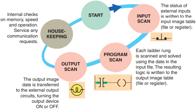
Figure 1 illustrates a single PLC operating cycle consisting of the input scan, program scan, output scan, and housekeeping duties. Because the inputs can change at any time, it constantly repeats this cycle as long as the PLC is in the RUN mode.
The time it takes to complete a scan cycle is called the scan cycle time and indicates how fast the controller can react to changes in inputs. The time required to make a single scan can vary from about 1 millisecond to 20 milliseconds.
If a controller has to react to an input signal that changes states twice during the scan time, it is possible that the PLC will never be able to detect this change. For example, if it takes 8 ms for the CPU to scan a program, and an input contact is opening and closing every 4 ms, the program may not respond to the contact changing state.
The CPU will detect a change if it occurs during the update of the input image table fi le, but the CPU will not respond to every change. The scan time is a function of the following:
- The speed of the processor module
- The length of the ladder program
- The type of instructions executed
- The actual ladder true/false conditions
The actual scan time is calculated and stored in the PLC’s memory. The PLC computes the scan time each time the END instruction is executed. Scan time data can be monitored via the PLC programming. Typical scan time data include the maximum scan time and the last scan time.
PLC Scan Cycle

process.
The scan is normally a continuous and sequential process of reading the status of inputs, evaluating the control logic, and updating the outputs. Figure 2 shows an overview of the data flow during the scan process. For each rung executed, the PLC processor will:
- Examine the status of the input image table bits.
- Solve the ladder logic in order to determine logical continuity.
- Update the appropriate output image table bits, if necessary.
- Copy the output image table status to all of the output terminals. Power is applied to the output device if the output image table bit has been previously set to a 1.
- Copy the status of all of the input terminals to the input image table. If an input is active (i.e., there is electrical continuity), the corresponding bit in the input image table will be set to a 1.
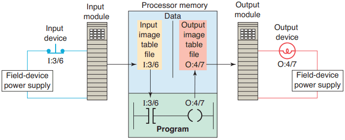
Figure 3 illustrates the scan process applied to a simple single rung program. The operation of the scan process can be summarized as follows:
- If the input device connected to address I:3/6 is closed, the input module circuitry senses electrical continuity and a 1 (ON) condition is entered into the input image table bit I:3/6.
- During the program scan, the processor examines bit I:3/6 for a 1 (ON) condition.
- In this case, because input I:3/6 is 1, the rung is said to be TRUE or have logic continuity.
- The processor then sets the output image table bit O:4/7 to 1.
- The processor turns on output O:4/7 during the next I/O scan, and the output device (light) wired to this terminal becomes energized.
- This process is repeated as long as the processor is in the RUN mode.
- If the input device opens, electrical continuity is lost, and a 0 would be placed in the input image table. As a result, the rung is said to be FALSE due to loss of logic continuity.
- The processor would then set the output image table bit O:4/7 to 0, causing the output device to turn off.

program.
Ladder programs process inputs at the beginning of a scan and outputs at the end of a scan, as illustrated in Figure 4. For each rung executed, the PLC processor will:
Step 1: Update the input image table by sensing the voltage of the input terminals. Based on the absence or presence of a voltage, a 0 or a 1 is stored into the memory bit location designated for a particular input terminal.
Step 2: Solve the ladder logic in order to determine logical continuity. The processor scans the ladder program and evaluates the logical continuity of each rung by referring to the input image table to see if the input conditions are met.
If the conditions controlling an output are met, the processor immediately writes a 1 in its memory location, indicating that the output will be turned ON; conversely, if the conditions are not met a 0 indicating that the device will be turned OFF is written into its memory location.
Step 3: The final step of the scan process is to update the actual states of the output devices by transferring the output table results to the output module, thereby switching the connected output devices ON (1) or OFF (0). If the status of any input devices changes when the processor is in step 2 or 3, the output condition will not react to them until the next processor scan.
Each instruction entered into a program requires a certain amount of time for the instruction to be executed. The amount of time required depends on the instruction. For example, it takes less time for a processor to read the status of an input contact than it does to read the accumulated value of a timer or counter.
The time taken to scan the user program is also dependent on the clock frequency of the microprocessor system. The higher the clock frequency, the faster is the scan rate. There are two basic scan patterns that different PLC manufacturers use to accomplish the scan function ( Figure 5).

Allen-Bradley PLCs use the horizontal scan by rung method. In this system, the processor examines input and output instructions from the first command, top left in the program, horizontally, rung by rung.
Modicon PLCs use the vertical scan by column method. In this system, the processor examines input and output instructions from the top left command entered in the ladder diagram, vertically, column by column and page by page. Pages are executed in sequence.
Both methods are appropriate; however, misunderstanding the way the PLC scans a program can cause programming bugs.
Thanks for reading about “PLC scan cycle”.