Linear motors move in a straight line with linear force and speed. Linear motion is needed in many types of systems, but linear motors aren’t commonly used by makers or professional engineers. That’s because these motors aren’t well-understood, there aren’t many manufacturers, and they’re expensive.
For these reasons, designers frequently obtain linear motion by connecting rotary motors to mechanical elements. As an example, the popular 3D printer RepRap obtains linear motion by connecting stepper motors to a timing belt.
Despite their rarity, linear motors are worth studying. When it comes to linear motion, linear motors provide better speed and precision than comparable electromechanical linkages—and depending on the motor, they can make more efficient use of power.
One major application of linear motors is transportation. Electric trains rely on linear motors to carry passengers and freight across long distances. Nations have spent billions on maglev (magnetic levitation) trains, and much of this effort has been devoted to linear motor research.
This article presents an overview of the topic of linear motors, dividing them into following categories:
- Linear actuators
- Linear synchronous motors & Linear induction motors
- Homopolar motors
Operation of Linear Actuators
If a currentcarrying wire is wrapped around an iron core, the wrapped core will behave like a magnet, with north and south poles. If current is reversed, the north and south poles switch sides. If current is turned off, the magnetic behavior stops.
If an iron core is only partially inserted into a current-carrying coil of wire, an interesting thing happens. The iron core (called a plunger) experiences a force that draws it fully into the coil. Figure 1 shows what this looks like.
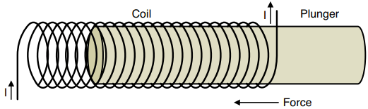
This type of device is referred to by many names, including solenoid, solenoid actuator, electric actuator, magnetic actuator, and linear actuator. Some sources refer to it as a linear motor, but from what I’ve seen, it’s more commonly called an actuator than a motor. For this reason, I’ll refer to it as a linear actuator .
This raises an important question—what’s the difference between an actuator and a motor? The answer is subtle and relates to the device’s function, not its structure. A motor is a device that converts energy into motion. An actuator is a specific type of motor whose motion is intended to control another mechanism.
For example, one common application of a linear actuator is to control the position of a mechanical switch. In this case, the actuator is called a relay. Other actuators open and close valves. In contrast, if a device’s purpose is simply to effect motion, such as spinning the wheels of a remote-controlled car or rotating the propellers of a quadcopter, it’s a motor, not an actuator.
Another difference between linear actuators and linear motors involves the nature of the input power. Every linear actuator I’ve encountered requires DC power, but as later sections will show, linear synchronous motors and linear induction motors rely on AC power.
Operation and Structure: To see how a linear actuator works, it’s important to grasp the concept of magnetic energy . Magnets and electromagnets can perform mechanical work. A device’s magnetic energy is the measure of how much work its magnets are capable of performing. If current flows through an empty coil of wire, the region inside the coil contains a small amount of magnetic energy.
However, if an iron plunger is fully inserted into the coil, the coil’s energy increases substantially. If the plunger is partially inserted, the region containing the plunger has more energy than the region that doesn’t. The force on the plunger equals this difference in energy divided by the distance between the plunger and the end of the coil.
The mathematical relationship for the force is complicated, but there are three important relationships to be aware of:
- Force increases with the square of the input current.
- Force increases with the square of the number of turns in the coil.
- Force increases with the cross-sectional area of the coil.
The force always pulls the plunger into the coil, but linear actuators can be constructed to push or pull the intended load. Figure 2 presents a linear actuator that pulls the load using a hook.
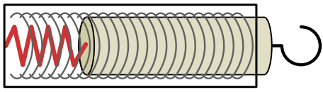
The metal casing concentrates the coil’s magnetic field inside the actuator. The plunger is attached to the casing with a spring. When current is sent through the coil, the force pulls in the plunger and compresses the spring. When the current is removed, the spring extends, returning the plunger to its original position.
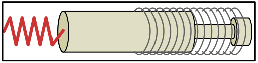
Figure 3 depicts a linear motor that pushes the intended load. Here, the right side of the plunger is attached to a non-ferromagnetic head that pushes outward when the coil is activated. When current is delivered to the coil, the force pushes the plunger into the coil. When current is removed, the spring contracts and returns the plunger to its original position.
Coilguns: In most linear motors, the plunger is attached to a mechanism so that it can be pushed or pulled repeatedly. However, if the plunger isn’t attached and the coil’s current is sufficiently strong, the motor can launch the plunger as a projectile. In this case, the plunger is referred to as a sabot and the motor is called a coilgun .
Compared to regular linear actuators, coilguns require a great deal of power. For a sabot the size of a thimble, a coilgun might require as much as 30 V at 15 A, but this power is only required for the tens or hundreds of milliseconds needed to propel the sabot out of the coil.
Because of the large power requirements over a short time, many designs rely on a bank of large capacitors to store energy. By discharging the capacitors simultaneously, the power circuit can supply enough electricity to launch the sabot.
Coilguns have fascinated electrically minded amateurs and professionals since the 1930s. A casual Internet search on the topic will lead to many hobbyist sites that discuss physics, parts, and circuit designs.
However, due to the large power draw, coilguns have never become practical tools. This doesn’t mean coilguns won’t be important in the future. As I write this, the United States military is investigating the use of coilguns to launch aircraft and mortar rounds from naval carriers. NASA is looking into coilgun-based launchers for its satellites and rockets.
Linear Synchronous Motors & Linear Induction Motors
These motors are discussed in the next post to decrease the length of this web-page.
Homopolar Motors
Homopolar motors are the oldest of the electrical motors, and the first was demonstrated in 1821. Like many of the motors, they can be rotary or linear. Linear homopolar motors have one famous (infamous?) application: the railgun. This section discusses this interesting topic, but first, it’s important to understand the principle behind homopolar motors.
Structure and Operation: When a current-carrying conductors come near a magnet, the result is physical force. In every motor we’ve seen so far, the conductors and the magnet are positioned close to one another but never come into contact.
But what if the magnet becomes part of the circuit loop? Magnets are conductors. What if the current-carrying conductor and the magnet were connected? In this case, the resulting force on the conductor will be the same. If the conductor can spin around the magnet, it will do so without the need of a brush.
The best way to understand how homopolar motors work is to see a demonstration, the most common of which involves a battery, a permanent magnet, and conductive wire. This has been performed countless times in classrooms, going back to the nineteenth century. If you search for homopolar motor demonstrations on the Web, you’ll probably find a video whose setup looks like that in Figure 4 .
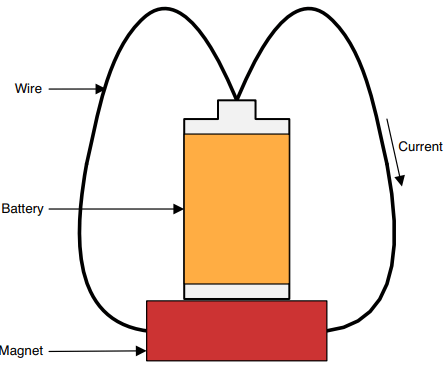
Current flows from the battery’s positive terminal to its negative terminal through the wires. Because the current-carrying wires are near the magnet’s field, a force is produced that rotates them around the magnet. It’s important to note that this demonstration drains the battery quickly.
The current’s direction and the magnet’s polarity (direction from north pole to south pole) remain the same throughout the motor’s operation. This is why the motor is called homopolar. ( Homos means “same” in Greek.)
Railguns: To generate strong forces, motors rely on strong permanent magnets (such as the rare-earth magnets) or strong electromagnets, which are made up of coils of wire surrounding an iron core. However, every current-carrying conductor exhibits a degree of magnetic behavior. As more current flows through the conductor, this magnetic behavior grows stronger.
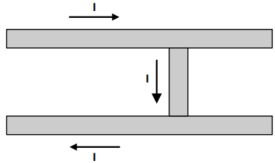
For example, consider the three conductors shown in Figure 5. The two long conductors are fixed in place and the short conductor is free to move between them. Each carries the same amount of current, denoted as I.
For normal levels of current, the magnetic behavior of the conductors is negligible. However, if the current grows large enough, up around 1000 A to 10,000 A, the magnetic behavior becomes strong enough to create a force that pushes the conductors apart.
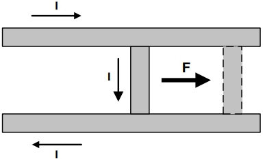
The two long conductors won’t move because they’re fixed in place, but the force on the short conductor will push it to the right. This is shown in Figure 6. The force increases with the current, and if the current is sufficiently large, the force can launch the small conductor as a projectile. In this case, the fixed conductors are referred to as rails and the structure is called a railgun.
The speed of a conventional bullet is limited by the chemical properties of gunpowder, but the speed of a railgun’s projectile is limited only by the amount of current.
For this reason, the U.S. Navy has experimented with railguns to launch projectiles from ships. In 2008, the Naval Surface Warfare Center demonstrated a railgun capable of launching a seven-pound conductive bullet at seven times the speed of sound.
The force exerted on the projectile is also exerted on the rails. Therefore, firing a railgun can cause significant damage to the gun itself. This damage and the extraordinary power requirements are the two main drawbacks of railgun technology.
It’s important to see the differences between railguns and the coilguns. A coilgun propels a ferromagnetic sabot through a coil of wire. The sabot doesn’t make contact with the coil, so there’s no damage to the system. However, the sabot’s speed is limited by the magnetic properties of the coil. In contrast, the conductive projectile of a railgun is only limited by the amount of current delivered to the rails.