An ideal transformer is one which has no losses (no iron loss and no copper loss) and no leakage flux i.e. all the flux produced by the primary winding is linking with the secondary winding.
In actual practice, it is impossible to make such a transformerbut to understand the concepts of transformer it is better to start with an ideal transformer and then extend to a practical transformer. In this article I am discussing the ideal transformer on load.
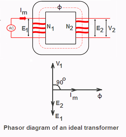
Consider an ideal transformer whose secondary is open as shown in the figure. When it is connected to AC supply voltage V1 a current Im flows through its primary winding.
Since the resistance of the primary coil is zero (i.e. it is purely inductive) the current Im lags behind the applied voltage V1 by 90o. The losses are zero (as assumed) and no load is applied to the transformer, therefore, the magnitude of current Im will be very small.
This current is called magnetizing current Im as it produces flux φ in the core. Because flux is produced by Im hence it is in phase with Im.
This alternating flux links with both secondary and primary windings. When this flux links with secondary winding it produces mutually induced EMF E2 in the secondary winding. When this flux links with primary winding it produces self-induced EMF E1 in the primary winding.
Both the EMFs (E1 and E2) oppose the cause (applied voltage V1) producing it (as per Lenz’s law). Hence these are shown in opposite direction in the phasor diagram.
V1 = primary applied voltage
E1 = self-induced EMF in the primary winding
E1 = V1 (because it is an ideal transformer with no resistance and reactance on primary side)
E2 = mutually induce EMF on the secondary side
V2 = secondary terminal voltage
V2 = E2 (because at no load I2 is zero)
I1 = Im, magnetizing current on primary side
I2 = 0 (no load)
Ideal Transformer on Load
When a load is applied to the secondary side of an ideal transformer, a finite value of secondary current (I2) starts flowing. The magnitude and phase of secondary current, I2 w.r.t. secondary terminal voltage, V2 depends upon the nature of the load.
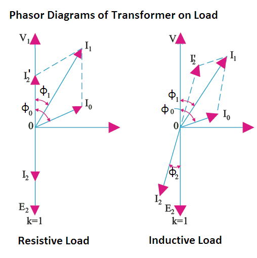
If the load is resistive, I2 is in phase with V2.
If the load is inductive (R-L) type, I2 lags V2 by some angle φ2.
If the load is capacitive (R-C) type, I2 leads V2 by some angle φ2.
When I2 flows, it sets up its own MMF (N2I2) and hence creates its own flux φ2.
However, φ2 opposes the main flux φm setup by magnetizing current (as per Lenz’s law).
This momentarily weakens the main flux φm and therefore primary back EMF E1 tends to decrease. Due to the reduction in E1, the difference between V1 and E1 increases and the additional primary current I2’ starts flowing. The I2’ component of primary current is called load component of the primary current.
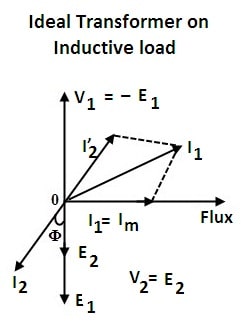
The current component I2’, sets up an MMF N1I2’ to counter the effect of secondary produced MMF N2I2
i.e N1I2’ = N2I2
or I2’ = N2I2 / N1 = KI2
and it is 180o out of phase with I2. The net primary current I1 is phasor sum of I2’ and Im (because Iw is zero in an ideal transformer).
Thus due to load on the secondary side, the primary current of the transformer increases to supply the additional power to the load.
Since, winding resistance of an ideal transformer is zero, therefore, its voltage regulation will be zero and its efficiency will be 100%.
Phasor Diagrams of Transformer on Load
Transformer | All Posts
- Ideal Transformer
- Construction of Three Phase Transformer
- Types of Transformers
- Equivalent Resistance and Reactance of Transformer
- Equivalent Circuit of Single Phase Transformer
- Power Loss in a Transformer
- Open Circuit Test of Single Phase Transformer
- Short Circuit Test on Single Phase Transformer
- Transformer Efficiency
- Regulation of Transformer
- Autotransformer
- Instrument Transformers
- Polarity of Transformer Windings
- Significance of Vector Group of Transformer
- Buchholz Relay Construction | Working
- Why current transformer secondary should not be opened
- Dielectric Strength Test of Transformer Oil
- Transformer Moisture Removal Process
© https://www.yourelectricalguide.com/ ideal transformer on load.