Hi friends, in this article, I am going to discuss the polarity of transformer windings, if you are interested, keep reading.
Unlike DC system, there are no fixed positive and negative poles in AC system, and hence, transformers cannot have fixed positive and negative terminals.
The relative direction in which primary and secondary windings of a transformer are wound around the core determines the relative direction of the voltage across the windings.
Polarity of Transformer Windings
If the windings of the two coils of a transformer are wound in the same direction, the applied voltage and the induced voltage will have the same direction in both the windings.
In this case, induced voltage waveform in the secondary winding will be in phase with the applied voltage waveform. This condition is known as “no phase shift.”
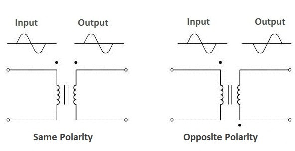
If the two coils of a transformer are wound in the opposite direction, the applied voltage and the induced voltage will have the opposite direction in both the windings.
In this case, secondary induced voltage waveform will be out of phase (by 180o) with the applied voltage waveform.
Similar polarity ends of the windings of a transformer are those ends that acquire simultaneously positive or negative polarity because of EMfs induced in them. These are indicated by dot convention as shown in Figure.
Knowledge of polarity of transformer windings is essential when single-phase transformers are connected in parallel or three-phase configurations. An understanding of polarity is also required to connect potential and current transformers to power metering and protective relays.
Polarity Test of Transformer
Assume, we want to determine the polarity of 220/12 V transformer. It may be determined by a simple voltage measurement, as follows:
- Place a connection between the high-voltage and low-voltage terminals as shown in Figure.
- Apply a low voltage, 220 volts, to the two high-voltage terminals.
- Measure the voltage between H2 and X1 terminals.
- If the voltage is lower than the voltage across the high-voltage terminals, the transformer has subtractive polarity and the jointed ends (H1, X2) are of same polarity.
- If it is higher, the transformer has additive polarity and the jointed ends (H1, X2) are of opposite polarity


This increase or decrease in measured voltage takes place because when we connect both the windings and apply voltage to the primary winding, it becomes an autotransformer.
When both the windings are wound in the same direction, the flux of each winding is also in the same direction i.e. it gets added and as a result, we get added voltage at the voltmeter.
Whereas when both the windings are wound in the opposite direction, the flux of each winding is also in the opposite direction i.e. it gets subtracted and as a result, we get subtracted voltage at the voltmeter.
Thanks for reading about polarity of transformer windings .
Transformer | All Posts
- Ideal Transformer
- Construction of Three Phase Transformer
- Types of Transformers
- Equivalent Resistance and Reactance of Transformer
- Equivalent Circuit of Single Phase Transformer
- Power Loss in a Transformer
- Open Circuit Test of Single Phase Transformer
- Short Circuit Test on Single Phase Transformer
- Transformer Efficiency
- Regulation of Transformer
- Autotransformer
- Instrument Transformers
- Polarity of Transformer Windings
- Significance of Vector Group of Transformer
- Buchholz Relay Construction | Working
- Why current transformer secondary should not be opened
- Dielectric Strength Test of Transformer Oil
- Transformer Moisture Removal Process
© https://yourelectricalguide.com/ transformer polarity.