The open circuit test of transformer is conducted to determine no-load loss or core loss and no-load I0 which is helpful in finding X0 and R0.
One winding of the transformer whichever is convenient but usually high voltage winding is left open and the other is connected to its supply of normal voltage and frequency.
The primary reason of performing open circuit test on the low voltage side is that it draws significantly large no load current for convenient reading. Also, it requires only low voltage supply which is easily available and safe to perform the test.
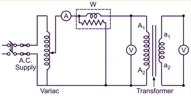
A wattmeter W, voltmeter V and an ammeter A are connected in the low voltage winding i.e. primary winding. With normal voltage applied to the primary, normal flux will be set up in the core, hence normal iron losses will occur which are shown by the wattmeter.
As the primary no-load current I0 is small copper loss at this current is negligibly small in primary and nil in secondary (as it is open). Hence, the wattmeter reading shows practically the core loss under no-load condition.
It should be noted that since I0 is itself very small, the pressure coils of the wattmeter and the voltmeter are connected such that the current in them does not pass through the current coil of the wattmeter.
Sometimes, a high-resistance voltmeter is connected across the secondary. In that case, the reading of the voltmeter gives the induced EMF in the secondary winding. This helps to find transformation ratio K.
Open Circuit Test Procedure
- Connect the circuit as shown in the figure.
- Keep the autotransformer at its minimum output voltage position.
- Switch on the power supply and adjust the autotransformer to get the rated supply voltage.
- Now note down the current and power shown by the ammeter and wattmeter respectively. Let these are Io and Wo.
- The wattmeter reads the no load input power to the transformer. The no load current of the transformer is very small as compared to full load current (about 3 to 5% of the full load value) and hence the copper loss in the winding connected to the supply is small.
- As the high voltage winding is kept open therefore the copper loss in that winding is zero. Therefore the total copper loss is very small and can be neglected. Hence the watt meter reading represents the iron losses.
i.e Wo = Pi = Iron losses
While performing the open circuit test of a single phase transformer, high voltage winding should not be touched because it may cause a serious electric shock.
Calculation of Parameters From Open Circuit Test
The two parameters which can be calculated from the open circuit test of transformer are Ro and Xo. They are calculated as follows.
Step 1: Calculate no load power factor (cos φo)
The wattmeter reads the real power input.
Therefore, Wo = VoIocos φo
or cosφo = Wo/VoIo
We can calculate φo from this.
Step 2: Calculate Im and Iw :
Im = Iosin φo
Iw = Iocos φo
Step 3: Calculate Ro and Xo
Ro = Vo/Iw Ω
Xo = Vo/Im Ω
The value of power factor of a transformer at no load is very small. Therefore the watt meter used while performing the open circuit test of a single phase transformer should be able to show accurate readings on small power factors.
Separation of Core Losses
The core loss of a transformer depends upon the frequency and the maximum flux density when the volume and the thickness of the core laminations are given. The core loss is made up of two parts
- hysteresis loss Wh = PBmax6f as given by Steinmetz’s empirical relation and
- eddy current loss We = QBmax2f2 where Q is a constant.
So, the total core loss = Wh + We = PBmax1.6f + QBmax2f2
If we carry out two experiments using two different frequencies but the same maximum flux density, then we will be able to find the constants P and Q and hence we can calculate hysteresis and eddy current losses separately.
Thanks for reading about “open circuit test of single phase transformer”.
Transformer | All Posts
- Ideal Transformer
- Construction of Three Phase Transformer
- Types of Transformers
- Equivalent Resistance and Reactance of Transformer
- Equivalent Circuit of Single Phase Transformer
- Power Loss in a Transformer
- Open Circuit Test of Single Phase Transformer
- Short Circuit Test on Single Phase Transformer
- Transformer Efficiency
- Regulation of Transformer
- Autotransformer
- Instrument Transformers
- Polarity of Transformer Windings
- Significance of Vector Group of Transformer
- Buchholz Relay Construction | Working
- Why current transformer secondary should not be opened
- Dielectric Strength Test of Transformer Oil
- Transformer Moisture Removal Process
© https://www.yourelectricalguide.com/ open circuit test on single phase transformer.