The power loss in transformer can be divided into two types namely the copper and the iron loss. The iron losses can be further classified into two types namely the hysteresis losses and the eddy current losses.
Copper Power Losses in Transformer
The total losses that take place in the winding resistance of a transformer are known as the ‘Copper losses’. These losses in a transformer should be kept as low as possible to increases the efficiency of the transformer.
To reduce the copper losses, it is essential to reduce the resistance of primary and secondary winding coils of the transformer i.e. size of the winding conductor is selected very carefully. These are also known as the variable losses as these are dependent on the square of load current.
To determine the copper losses, short circuit test on transformer is performed.
The total copper losses in transformer are:
= I12R1 + I22R2 = I12R01 = I22R02
Where, I1 , I2 = primary and secondary currents respectively,
R1, R2 = primary and secondary resistances respectively,
R01, R02 = equivalent resistances referred to primary and secondary respectively.
Iron Losses in Transformer
The power losses that take place in its iron core are known as the ‘Iron losses’. These losses occur due to alternating flux set up in the core.
In a transformer, flux set up in the core remains constant from no load to full load. Hence these power losses are independent of load and also known as constant losses of a transformer.
These losses have two components named hysteresis losses and eddy current losses. To determine the iron losses, open circuit test of transformer is performed.
Hysteresis Power Losses in Transformer
When a magnetic material is subjected to reversal of flux, power is required for the continuous reversal of molecular magnets. This power is dissipated in the form of heat and is know as ‘Hysteresis Loss’.
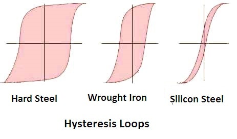
The hysteresis loss of a magnetic material depends upon its area of the hysteresis loop. Hence the magnetic materials such as silicon steel, which has very small hysteresis loop area, are used for the construction of the core to minimize the hysteresis loss in a transformer.
The hysteresis loss (Ph = KhVfBm1.6) is frequency dependent. As we increase the frequency of operation, this loss increases proportionally.
Eddy Current Losses in Transformer
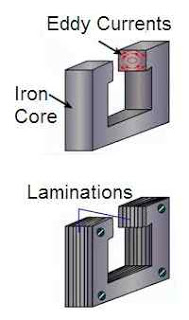
Due to alternating flux in a transformer, some EMF is induced in the transformer core. This induced EMF causes some currents to flow through the core of the transformer. These currents are known as eddy currents.
The core of transformer has some finite resistance. Hence due to the flow of eddy currents, some power losses take place and are known as ‘Eddy current losses’
(Pe = KeVft2Bm2).
The eddy current losses in transformer are minimized by using the laminated core. These laminations are insulated from each other by mean of a thin varnish coating. Hence each lamination acts as a separate core of a small cross sectional area, offers a high resistance to the flow of eddy currents.
Therefore, with the use of laminations in the core, eddy currents and eddy current losses are reduced. These losses are also frequency dependent. They are directly proportional to the square of operating frequency.
How to Calculate Copper Losses in Transformer
Example: The primary and the secondary windings of a 500kVA transformer have resistance of 0.42 ohms and 0.0011 ohms respectively.
The primary and the secondary voltages are 6600V and 400V respectively. Calculate copper losses at the full load and the half load.
Solution: Transformer rating = 500kVA
Primary resistance, R1 = 0.42Ω
Secondary resistance, R2 = 0.0011Ω
Primary voltage, E1 = 6600V
Secondary voltage, E2 = 400V
Transformation ratio, K = E2/E1 = 400/6600 = 2/33
Primary resistance referred to secondary,
R1’ = K2R1 = (2/33)2 x 0.42 = 0.00154 Ω
Total resistance referred to secondary, R02 = R2 + R1’ = 0.0011 + 0.00154 = 0.00264 Ω
Full load secondary current, I2 = (kVA x 103)/E2 = (500 x 103)/400 = 1250A
Copper losses at full load = I22R02 = (1250)2 x 0.00264 = 4125W
Secondary current at half load = 1250/2 = 625A
Copper losses at half load = (625)2 x 0.00264 = 1031.25W
Transformer | All Posts
- Ideal Transformer
- Construction of Three Phase Transformer
- Types of Transformers
- Equivalent Resistance and Reactance of Transformer
- Equivalent Circuit of Single Phase Transformer
- Power Loss in a Transformer
- Open Circuit Test of Single Phase Transformer
- Short Circuit Test on Single Phase Transformer
- Transformer Efficiency
- Regulation of Transformer
- Autotransformer
- Instrument Transformers
- Polarity of Transformer Windings
- Significance of Vector Group of Transformer
- Buchholz Relay Construction | Working
- Why current transformer secondary should not be opened
- Dielectric Strength Test of Transformer Oil
- Transformer Moisture Removal Process
© https://www.yourelectricalguide.com/ power losses in transformer.