The induction motor is equivalent to a rotating transformer. Hence, we can draw the induction motor equivalent circuit with the help of equivalent circuit of the transformer.
The basic equivalent circuit of induction motor is shown in Fig. which is very similar to that of a transformer.
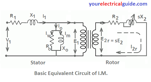
Here R1 and X1 are the per phase values of stator resistance and stator leakage reactance.
E1 is per phase stator voltage and N1 the number of stator turns per phase whereas R2 rotor resistance per phase and sX2 is rotor reactance per phase in running condition.
- where, s = slip, X2 = rotor reactance at standstill.
The resistance Ro is the no-load resistance per phase, that represents the resistance for core losses and Xo represents the magnetizing component of the no-load stator current similar to the magnetizing component of the no-load primary current of the transformer.
V1 is the per phase stator supply voltage. E1 is the per phase stator induced voltage
E2r = sE2 is the per phase rotor induced EMF (in running condition)
- where, s = slip, E2 = induced EMF in rotor at standstill.
The rotor current I2r is given by,
I2r = sE2/ [R22 + (sX2)2]1/2
= E2/ [(R2/s)2 + X22]1/2
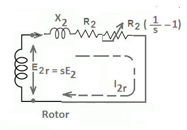
From the above expression, it is clear that the rotor circuit actually consists of a fixed resistance R2 and a variable reactance sX2, connected across E2r = sE2 is equivalent to a rotor circuit having a fixed reactance X2 connected in series with a variable resistance R2/s and supplied with constant voltage E2.
We can express resistance R2/s in two parts as follows:
R2/s = R2 + R2(1/s – 1)
- were, the first part R2 is the rotor resistance and represents the rotor copper losses.
- and the second part R2(1/s – 1) is the load resistance RL. It is the electrical equivalent of the mechanical load on the motor. It is the electrical power that is converted into the mechanical power by the motor.
Hence equivalent rotor circuit of the induction motor can be drawn as under.
Equivalent Circuit of Induction Motor Referred to Stator
We can draw the equivalent circuit of induction motor referred to stator or rotor side like that of a transformer.
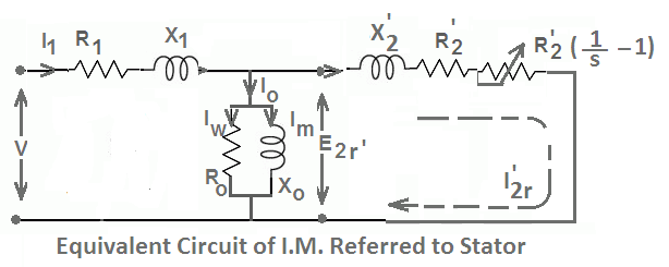
We know that, transformation ratio, k = E2/E1
All the rotor parameters are transferred to the stator side as follows:
E2r’ = E2r/k
I’2r = kI2r
X’2 = X2/k2 and R’2 = R2/k2
Approximate Equivalent Circuit of Three Phase Induction Motor
The no-load circuit components Ro and Xo can be shifted to the left of R1 and X1 to obtain the approximate equivalent circuit of the induction motor.
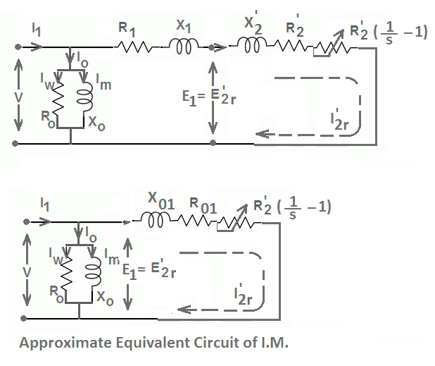
Here, Ro1 = R1 + R’1 is equivalent resistance referred to the stator and Xo1 = X1 + X’1 is equivalent reactance referred to the stator.
Three Phase Induction Motor | All Posts
- Three Phase Induction Motor Construction
- Rotating Magnetic Field in Three Phase Induction Motor
- Three Phase Induction Motor Working Principle
- Induction Motor Slip
- Torque Formula for Induction Motor
- Torque Slip Characteristics of Induction Motor
- Losses in Induction Motor
- Induction Motor Tests
- Starting Methods of Induction Motor
- Double Squirrel Cage Induction Motor
- Speed Control of 3 Phase Induction Motor
- What is a variable frequency drive?
- Autotransformer Starter Working Principle
- Thermal Overload Relay Working
- Linear Induction Motor Working | Applications
© https://yourelectricalguide.com/ equivalent circuit of induction motor.