A transistor can also act as a switch and can turn ON and OFF power in an electrical load. The action of the transistor, while using a transistor as a switch is explained below:
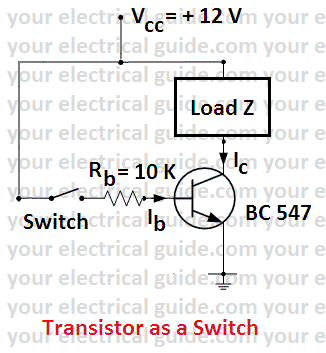
- Consider an NPN transistor as shown in Figure. Z is the load in the collector circuit and the controlling switch S is in the base circuit.
- When switch S is closed, the base-emitter junction is forward biased and the transistor conducts i.e. current starts flowing through load Z.
- Since the base current is much smaller than the load current (collector current), therefore, we can switch ON a much large current with a small current.
- This operation of the transistor is similar to relay where with a small relay coil current, we can control much heavier load current. Here, the base circuit corresponds to relay coil and the transistor to the contacts of the relay.
- The most important point to note here is that there are no moving contacts in a transistor and the conduction is by transistor action.
- When switch S is OFF, the base current is zero. However, the collector current is not zero since a little leakage current always flows through the collector. The leakage current is only a few µA for silicon transistor but is several hundred µA for a germanium transistor.
Switching Action of a Transistor
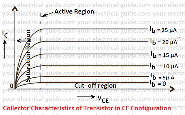
To understand the switching action of a transistor in detail, consider the collector characteristics for a CE configuration as shown in Figure. Let us describe the various switching conditions on these characteristics.
OFF region: When the base circuit is open, the transistor (i.e. switch) is said to be in OFF condition and power to the load is cut off. In the OFF state, the transistor operates in the cut-off region.
In the OFF condition, Ib = 0 and the collector current is equal to the collector leakage current (Iceo).
ON region: When the base circuit is closed and current flows, the transistor (i.e. switch) is said to be in ON condition. In the ON condition, saturation current flows through the load and Vce = Vknee.
In the ON state, the transistor operates in the saturation region. It is called the saturation region because the current Ic no longer depends upon the input current Ib.
Active region: The region, lying between the ON and OFF conditions is called an active region.
Transistor as a Switch | Important Terms
The following are the important terms which are much used while using a transistor as a switch:
Saturation Collector (load) Current: The maximum collector current, for a particular load in a transistor, is called saturation collector current. Under such conditions, the transistor is said to work in the saturation region.
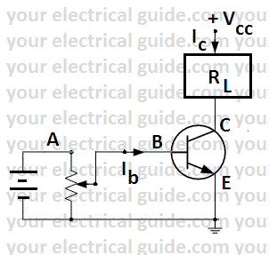
Consider an NPN transistor containing a load RL in its collector circuit as shown in Figure. As the base current is increased, the collector current also increases. This increase in collector current is β times the base current.
However, with the increase in collector current, the voltage across the load RL also increases. Consequently, Vce goes on decreasing.
When Vce drops to knee voltage (Vknee = 0.5 V for Ge and 1.0 V for Si), any further increase in collector current is not possible since β decreases sharply when Vce falls below knee voltage.
This maximum collector current is called saturation current i.e.
Collector saturation current = (Vcc – Vknee)/ RL
When, Vce drops to knee voltage, switch off the circuit and measure the value of resistance between points A and B marked in the circuit. It is the value of base resistance (Rb) to be connected to the base to use the transistor as a switch.
Power Amplification: Transistors, like relays, can handle large power in the load placed in the collector by supplying a small power in the base circuit.
It is because base-emitter voltage required to turn ON power in load placed in the collector is very small (0.5 V for silicon transistor and 0.2 V for Ge transistors).
The ratio of output power to the input power of a transistor is called power amplification.
Power Loss in Transistor when Used as Switch
It is important to know the power loss in a transistor during switching operations due to the following reasons:
- To determine the power handling capacity of the transistor. This enables us to select a transistor for a particular switching operation.
- To find the efficiency of the system. The power loss in the transistor reduces the efficiency of the system. The power loss in the transistor is given by:
Power loss = Vce x Ic
Let us now discuss the power loss in OFF and ON conditions.
OFF Condition: In this condition, the collector current is very small and is equal to collector leakage current (Iceo).
However, under such conditions, Vce = Vcc as the voltage drop in the load due to Iceo is negligible. Hence, power loss in a transistor in the OFF condition is given by,
Poff = Vce x Ic = Vcc x Iceo
As Iceo is extremely small as compared to full load current that flows in the ON condition, therefore, the power loss in the transistor in OFF condition is quite small. In other words, the transistor has very high efficiency as a switch in the OFF condition.
ON Condition: In this condition, the collector current is large and is equal to the saturation current. However, under such conditions, Vce is quite small and is equal to Vknee. Hence, power loss in the transistor in ON condition is given by,
Pon = Vce x Ic = Vknee x Ic sat
This is also quite small. Therefore, the efficiency of a transistor in ON condition is also very high.
Application of Transistor as a Switch
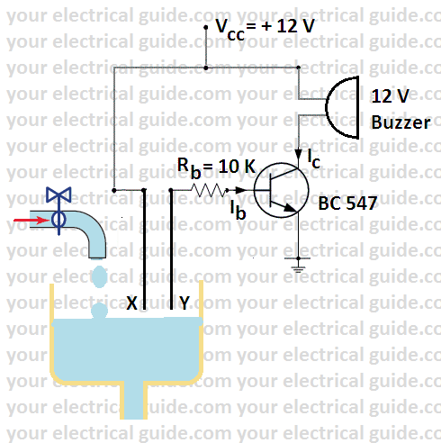
It is an arrangement which gives an indication by the ringing of the buzzer when the water tank becomes full. A simple circuit is shown in Figure. The base wires are taken to the tank. The terminals of the base wire are held quite close.
When the water level reaches up to the base terminals, the base circuit is completed. This starts current in the buzzer connected in the collector circuit and the buzzer starts ringing.
While controlling an inductive load by a transistor, a free wheeling diode is connected across load to protect the transistor. I have discussed the working of the free wheeling diode earlier.
Advantages of Using Transistor as a Switch
- No moving parts, hence little wear and tear.
- Trouble free service due to solid state technology.
- Noiseless operation.
- Has an infinite life.
- Fast operation ( up to 109 operations per second).
- Requires little maintenance.
Related Posts
- P N Junction Diode Theory | Working
- Characteristics of PN Junction Diode
- Working Principle of Rectifier
- Zener Diode Characteristics
- Zener Diode as Voltage Regulator
- JFET | Junction Field Effect Transistor Basics
- JFET Construction and Working
- Op Amp | Operational Amplifier Basics
- Transistor as a Switch
- Buck Converter Working
- Buck Boost Converter Working
- Astable & Monostable Operation of 555 Timer Chip
- Light Sensitive Devices
- Industrial Applications of Ultrasonic Waves
- Radar Working Principle
- Electrical Timer & Timer Charts
- RLC Parallel & RLC Series Circuit Resonance
- Types of Capacitors
© www.yourelectricalguide.com/ using a transistor as a switch theory.