Hi friends,
In this article, I am providing you some basic information about the industrial applications of ultrasonic waves. So keep reading.
The term ultrasonic is used in acoustics to denote the frequencies which are beyond the range of human hearing. Thus; ultrasonic waves are sound waves of frequencies above 20,000 c/s.
By using modern methods of generation, it has become possible to produce ultrasonic wave vibrations up to frequencies of about 5 x 10⁵ c/s. The wavelength of ultrasonic waves in air ranges from about 1.6 cm to 6 x10⁻⁵ cm and in solids from 20 cm to 8 x 104 cm. The shortest ultrasonic waves have nearly the same wavelength as visible light.
The production and use of ultrasonic waves utilize electronic circuits. These are today being used for numerous applications in industry, communication systems and chemical and medical sciences. Testing of materials for flaw detection by ultrasonic waves is being widely used.
There are numerous ways of producing ultrasonic waves depending upon the application and the required wavelength such as the Galton whistle gas current generator, magnetostriction generator, piezoelectric generator, etc.
The piezoelectric generator is the most common type of generator for producing ultrasonic waves which converts high-frequency electrical oscillations into mechanical oscillations. If a thin quartz plate is cut in Y – Z plane and an alternating voltage is applied along the X or electric axis, this results in compression of the plate in a one-half cycle of the a.c. voltage and expansion during the other half. The plate is thus set into elastic oscillations of the same period as the field.
The amplitude of oscillations is maximum when the frequency of the applied electric field equals the natural mechanical frequency. On account of the longitudinal and transverse reciprocal piezo-effects, the following two types of oscillations are possible:
- Vibrations in X direction. These are called the thickness vibrations.
- Vibrations in Y direction. These are called the length vibrations.
Both these forms of oscillation are used for the production of sound waves. Thickness oscillations are generally used for producing ultrasonic waves at as low a frequency as 200 kc/s corresponding to a quartz thickness of 13.6 mm.
Longer wave-length waves are produced by length vibrations but then it is no longer possible to radiate the sound energy from the larger section. The upper limit of the frequency produced by piezo-electric quartz vibrator is about 50,000 kc/s produced by a 0.054 mm thick quartz cut at right angles to the X-axis. Still higher frequencies are produced by using tourmaline plate.
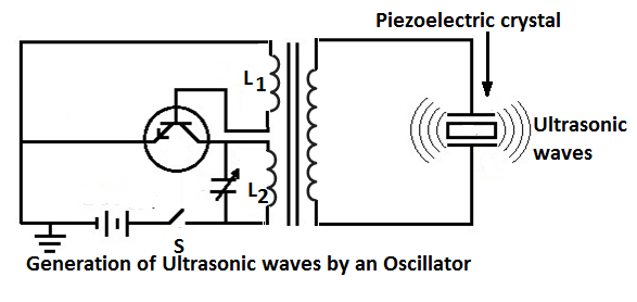
A piezoelectric crystal may be (most conveniently set in vibration by simply putting it in parallel with the oscillatory circuit of any electronic oscillator. The figure shows one such arrangement. The oscillator frequency is adjusted to match the natural frequency of the crystal plate. The amplitude of ultrasonic vibrations so produced is then proportional to the voltage applied to it. To avoid sparking at the quartz plate, a spark gap is put in parallel with it.
Industrial Applications of Ultrasonic Waves
Ultrasonics as a Means of Communication
Ultrasonic waves are used for sound signaling. The high-frequency sound waves are readily formed into a beam and sent in the desired direction. A quartz plate vibrating in thickness mode radiates the sound in a direction almost at right angles to the plate surface.
The beam of sound gets more and more narrow as the radius of the plate is increased in relation to the wavelength of the radiated sound. For example, at 600 kc/s, a plate of 3.5 cm dia. is enough to confine the sound within an angle of 5o. Such narrow beams can not be attained in the audible frequency range.
Another advantage of ultrasonics is that a low power source can radiate ultrasonic waves of great intensity. Submarine ultrasonic transmitters have been developed for detecting the presence of icebergs or submarines and for the ship to ship signaling. The typical range is about 15 km and the accuracy of direction of sound is about 1°. The signaling is done either by Morse or by telephony; the quartz vibrations being modulated by the speech frequencies.
The position of ships and submerged submarines are located on the echo principle in the manner of the conventional pulse radars. Pulses of ultrasonic signals arc sent out at short intervals; the returned echo is received in the ultrasonic receiver and the time interval between the transmitted and received signals is noted. Knowing the velocity of sound in water (app. 1200 m/s), the distance can be calculated.
Determination of Depth of Sea/Lakes
This also uses the echo principle. A piezo-electric transmitter is typically energized at a frequency of about 40 kc/s by a high-frequency impulse lasting about 1 millisecond. The receiver also uses a piezo-crystal followed by an amplifier and time measuring device.
Ultrasonic Flaw Detection Methods
Ultrasonic flaw detection methods are being extensively used in industry for the location of fractures, cavities, stratifications porosity, slag, etc. produced during the process of casting.
These defects may, no doubt be detected by using well-established methods. However, the X-ray method suffers from the drawbacks of small penetration and the use of high voltages while the magnetic testing method has the drawback of the restricted area of application. The gamma-ray testing needs unwieldy apparatus.
The ultrasonic testing is cheap, convenient and sufficiently reliable. The high-frequency ultrasonic vibrations propagate in a homogeneous solid in a straight line and the waves are totally reflected at the boundary of the solid with air. The ultrasonic flaw detection is also based on the principle of reflected signal pulses.
Pulses at high frequencies of 0.8 to 2.5 MHz for inspection of steel, aluminum, and brass articles are used. Lower frequencies are used for inspection of coarse grain materials, such as cast iron, porcelain, concrete, timber, plastic goods, etc.
Generally, a single probe or transducer is used. This transducer first acts as a transmitter sending out a pulse into the article to be inspected and then acts as a receiver to receive the ultrasonic echo pulses reflected from the flaw and the far end of the material.
These reflected pulses are converted into electric pulses of the same frequency as the sound waves. These are then amplified and displayed in the form of a series of pips or pulses on the screen of a cathode-ray tube.
The first pulse corresponds to the transmitted pulse, the subsequent pulses to the flaws within the body, and last of all the echo pulse from the far end is received. The distance of the flaw can be easily worked out.
The equipment can be used for detection of flaws as deep as 10 meters from the front surface. However, the drawback of the pulsed echo detector is that there exists a dead-zone about 2 to 5 mm deep, close to the front surface. Flaws in this zone are not detectable since the echos obtained from them return to the transmitter while it is still transmitting the pulses and is not yet switched to receiving.
Ultrasonic Surface Waves
These are used to detect surface fractures. These surface waves moving along the surface under study are very sensitive to the slightest inhomogeneities and faults on the surface. Thus, ultrasonic surface waves of frequency 2.5 Mc/s can detect fractures 0.05 mm in depth up to a distance of 60 cm. Ultrasonic surface waves are used for detection of fatigue fractures in the blades of turbines and compressors, for testing of aluminum sheets used in aircraft, etc.
Detection of Fatigue by Ultrasonic Flaw Detector
The structure of the metal in shafts, rods, and beams subjected to alternating loads, changes gradually due to fatigue. The faces of the grains get displaced and micro-cavities are formed. These changes are not detected by conventional flaw detectors but are detected by a special pulsed instrument with calibrated attenuation and timing marks. The rates of propagation and the attenuation of ultrasonic waves are noted and compared with those of standard specimen of the same material with no fatigue.
Thanks for reading about “industrial applications of ultrasonic waves”.
Related Posts
- P N Junction Diode Theory | Working
- Characteristics of PN Junction Diode
- Working Principle of Rectifier
- Zener Diode Characteristics
- Zener Diode as Voltage Regulator
- JFET | Junction Field Effect Transistor Basics
- JFET Construction and Working
- Op Amp | Operational Amplifier Basics
- Transistor as a Switch
- Buck Converter Working
- Buck Boost Converter Working
- Astable & Monostable Operation of 555 Timer Chip
- Light Sensitive Devices
- Industrial Applications of Ultrasonic Waves
- Radar Working Principle
- Electrical Timer & Timer Charts
- RLC Parallel & RLC Series Circuit Resonance
- Types of Capacitors