A resonance circuit consists of a capacitor and an inductor. It also has some resistance. Either this resistance may be the effective resistance of the coil itself or connected externally to create some desired effect.
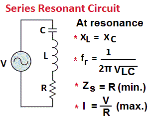
A resonance RLC series circuit is shown in Figure. Here, a capacitor C and an inductor L are connected in series and are connected to a voltage source. The resistance R represents the coil resistance. Its value is usually very small and is generally neglected as compared to the other impedances. The capacitor C is assumed to be lossless. The frequency of the source can be varied.
Depending upon the frequency of the source voltage, these circuits either may behave as a capacitive circuit or an inductive circuit. But at a particular frequency, inductive reactance will become equal to the capacitive reactance. In this state, the circuit will behave like a purely resistive circuit. This phenomenon is known as resonance and the corresponding frequency is known as the resonance frequency.
RLC Series Circuit Resonance
At a given frequency f, the reactance of the inductor and the capacitor will be:
XL = 2πfL and XC = 1/2πfC
And the total impedance of the circuit will be:
Z = [(R2) + (XL – XC)2]1/2
From these equations, we can understand easily that XL increases linearly with the frequency whereas the reactance XC varies inversely with frequency.
Now if we vary the frequency of source uniformly, we find at a particular frequency very high current flows through the circuit. This is so because, at this frequency, the circuit offers minimum impedance to the voltage source and this frequency is known as the resonance frequency.
At this frequency, XL = XC and cancels each other, therefore, Z = R. This is the minimum possible impedance of the circuit.
Below the resonant frequency, XC > XL, the circuit offers capacitive reactance to the source. And above the resonant frequency, XL > XC, the circuit offers inductive reactance to the source.
At the resonance, XL = XC
Or 2πfrL = 1/2πfrC
Or Resonance frequency fr = 1/2π√(LC)
It is clear from the above discussion that the current is a series RLC resonance circuit is maximum at the resonant frequency and it decreases on either side of this frequency. Thus this circuit has a property of selecting signals of one particular frequency.
Quality Factor of Coil – Q
The circuit resistance R plays an important role in the signal selectivity. Because the rate at which the circuit current decreases as we move away from the resonant frequency depends upon the resistance of the circuit.
If the resistance in the circuit is low, the current falls very sharply as we move away from the resonance frequency. However, the resonance frequency of the circuit is not affected by the resistance of the circuit.

Generally, the resistance of a resonant circuit is an integral constituent of the inductor used. The coils of the same inductance but different resistance values will have different selecting properties. Thus, the resistance of the coil determines the quality of the inductor used. In technical terms, it is called quality factor of the coil.
In the context of a coil, the ratio of the inductive reactance to its resistance is known as Q of the coil. Similarly, in the context of a resonance circuit, the ratio of reactance to the circuit resistance is known as Q of the resonance circuit.
If the circuit resistance is only due to the coil, then Q of the circuit and the Q of the coil will be the same.
While calculating the circuit Q at resonance, either reactance (XL or XC) can be used since they are equal. Therefore,
Q = XL/R = 2πfrL/R
A series resonance circuit with high quality factor provides good frequency discrimination. In simple words, Q is the measure of the ability of a resonant circuit to select or reject a band of frequencies. The higher the Q of a resonance circuit, the greater its ability as a frequency selector will be.
RLC Parallel Circuit Resonance
A parallel RLC resonance circuit is shown in Figure. Here, an inductor and a capacitor are connected in parallel to each other, with respect to the supply source. The resistance R represents the coil resistance. Its value is usually very small and is generally neglected as compared to the other impedances. The capacitor C is assumed to be lossless. The frequency of the source can be varied.

The current through the inductance will lag the supply voltage V by 90o and the current through the capacitor will lead by 90o. Thus they will cancel each other partially or completely according to the magnitude of the branch currents.
At higher frequencies, XC < XL then IC > IL and the circuit is capacitive. Whereas At lower frequencies, XL < XC then IL > IC, and the circuit is inductive.
At the resonance, XL = XC, the inductive current and the capacitive current will be equal (but opposite in phase). So they will cancel each other completely. In other words, no current will flow through the circuit. It will offer very high impedance. However, it is an ideal condition, practically, a very small amount of current will flow.
So the impedance at resonance is maximum and as we go off resonance, the impedance drops. The value of resistance determines the height and steepness of the impedance curve. If the resistance is more, the height of the impedance curve reduces and the curve flattens out.
Bandwidth of Resonance Circuit
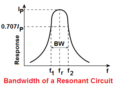
So every resonant circuit can discriminate between the frequency at resonance and those not at resonance. This discriminating property of the resonant circuit is expressed in terms of bandwidth.
The bandwidth of a resonance circuit is the total number of hertz above and below the resonant frequency that gives the practically same response as at the resonance frequency itself. This band is also known as the pass-band of the circuit.
It can be in terms of line current for a series resonance circuit and in terms of impedance for a parallel resonance circuit.
The frequency response of a resonant circuit is shown in Figure. The effective limits of the pass-band are taken at the points on the response curve corresponding to 70.7% of the peak value.
Since the Q of the circuit determines the overall steepness of the curve. Therefore the bandwidth of circuit can be expressed in terms of Q as follows:
Bandwidth = (f2 – f1) = fr/Q.
Thanks for reading about “rlc series circuit resonance”.
Related Posts
- P N Junction Diode Theory | Working
- Characteristics of PN Junction Diode
- Working Principle of Rectifier
- Zener Diode Characteristics
- Zener Diode as Voltage Regulator
- JFET | Junction Field Effect Transistor Basics
- JFET Construction and Working
- Op Amp | Operational Amplifier Basics
- Transistor as a Switch
- Buck Converter Working
- Buck Boost Converter Working
- Astable & Monostable Operation of 555 Timer Chip
- Light Sensitive Devices
- Industrial Applications of Ultrasonic Waves
- Radar Working Principle
- Electrical Timer & Timer Charts
- RLC Parallel & RLC Series Circuit Resonance
- Types of Capacitors