Light Sensitive Devices
Light-sensitive devices include photo cells, solar cells, photo-diodes, and photo-transistors.
Photo Cell
It is a light-sensitive device in which the internal resistance changes with a change in light intensity. The resistance change is not proportional to the light striking it.
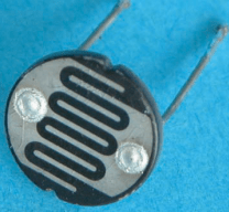
The photo cell is made from light-sensitive material such as cadmium sulfide (CdS) or cadmium selenide (CdSe).
The photo cell is more sensitive to light than any other device. The resistance can vary from several hundred million ohms to several hundred ohms. But it gives slow response to light change.

Figure 2 shows the schematic symbols used to represent a photo cell. The arrows indicate a light-sensitive device.
It is useful for llight senstive applications. It is used in light meters for photographic equipment, instruction detectors, automatic door openers, and various kinds of test equipment to measure light intensity.
Photo Voltaic Cells or Solar Cells
Photo voltaic cells are unique diode devices that generate a voltage when illuminated. These devices convert light energy directly into electrical energy. No outside source of electricity is needed to produce current.

Basic construction is very similar to that of a junction diode. In operation with no light applied, the cell will not cause a current flow. Essentially, this means that the junction is not being properly biased.
However, when light is applied, an interesting condition can be observed. Photocurrent (IPH) will flow in the circuit because of the photovoltage (VPH) that is developed across the junction. VPH is due to the generation of new electron-hole pairs in the depletion region.
Electrons move into the N material because of its normal positive ion concentration. Holes are likewise swept into the P material because of its negative-ion content. This action causes the N material to immediately take on a negative charge and the P material to take on a positive charge. The P-N junction therefore responds as a small voltage cell. Because of this, photovoltaic cells are often called solar cells or sun batteries.
Photovoltaic cells are generally classified as direct energy power converters. They will supply electrical power to a load device when light is applied. The operational efficiency of this device is based on the developed electrical power output divided by the light power input.
Photo-diodes
A photo-diode is a P-N junction device that will conduct current when energized by light energy. This device is designed for operation in the reverse bias direction. An external voltage source is required to reverse bias the device. These devices have a very fast response time. They are used in high-speed computer counting circuits and as movie projector sound track pickups.

We know that a very small reverse current flows when a diode is reverse biased. This leakage current is primarily caused by thermally generated electron-hole pairs in the depletion region. Current carriers of this type are swept across the junction by the reverse-biased electric field. An increase in junction temperature causes a corresponding increase electron-hole pair generation. This in turn causes an increase in leakage current.
The same effect takes place when light energy is applied to a P-N junction. Light travels in small bundles of energy called photons. When photons are absorbed by the P-N junction, their energy is used to free new electron-hole pairs. Increasing the intensity of light causes a reverse-biased photodiode to become more conductive. Characteristically, the reverse current of a photodiode increases with the intensity of light.
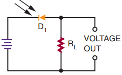
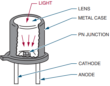
Photo-transistor
A photo-transistor is constructed like other transistors. It has three leads (emitter, base, and collector). It resembles a standard NPN transistor.
The transistor conduction depends on light falling on the base. The base lead is seldom used. When it is used, its purpose is to adjust the turn-on point of the transistor.
It is used like a photo-diode and packaged like a photo-diode, except that it has three leads (emitter, base, and collector).
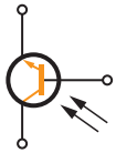
Photo-transistors can produce higher output current than photo-diodes. Their response to light changes is not as fast as that of the photo-diode.
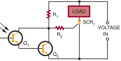
Applications include photo-tachometers, photographic exposure controls, flame detectors, object counters, and mechanical positioners.
Photo-transistors are now available that have a photo-diode and a transistor combined in a single device.
Optical Coupler
An optical coupler consists of an LED and a phototransistor. They are coupled by the light beam produced by the LED. The signal to the LED can vary, which in turn varies the amount of light available. The phototransistor converts the varying light back into electrical energy. An optical coupler allows one circuit to pass a signal to another circuit while providing a high degree of electrical insulation.
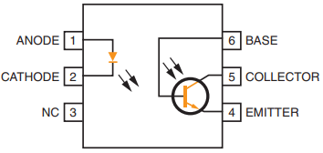
Above Figure shows an LED used in conjunction with a photo-transistor to form an optical coupler. Both devices are housed in the same package.
Related Posts
- P N Junction Diode Theory | Working
- Characteristics of PN Junction Diode
- Working Principle of Rectifier
- Zener Diode Characteristics
- Zener Diode as Voltage Regulator
- JFET | Junction Field Effect Transistor Basics
- JFET Construction and Working
- Op Amp | Operational Amplifier Basics
- Transistor as a Switch
- Buck Converter Working
- Buck Boost Converter Working
- Astable & Monostable Operation of 555 Timer Chip
- Light Sensitive Devices
- Industrial Applications of Ultrasonic Waves
- Radar Working Principle
- Electrical Timer & Timer Charts
- RLC Parallel & RLC Series Circuit Resonance
- Types of Capacitors